80S-2080F480F4-680F5 User’s Manual.pdf - 第523页
9 Maintenance SIPLACE 80S-20/F4/F4-6/F5 User’s Manual 9.6 IC Head (SIPLACE 80F4/80F4-6/F5) Edition 03/98 from Software Version SR.404.xx 9 - 74 - Sequence of work in Fig. 9.6.10 A Pull o ff the sle eve. B Remo ve the dia…
SIPLACE 80S-20/F4/F4-6/F5 User’s Manual 9 Maintenance
Edition 03/98 from Software Version SR.404.xx 9.6 IC Head (SIPLACE 80F4/80F4-6/F5)
9 - 73
- Sequence of work in Fig. 9.6.9
A Clean all the supporting surfaces with a dry brush.
B Dry clean the annular surface of the sleeve.
C Rub a little talcum powder into the supporting surface of the diaphragm.
D Clean the suction hole.
E Check the suction surface.
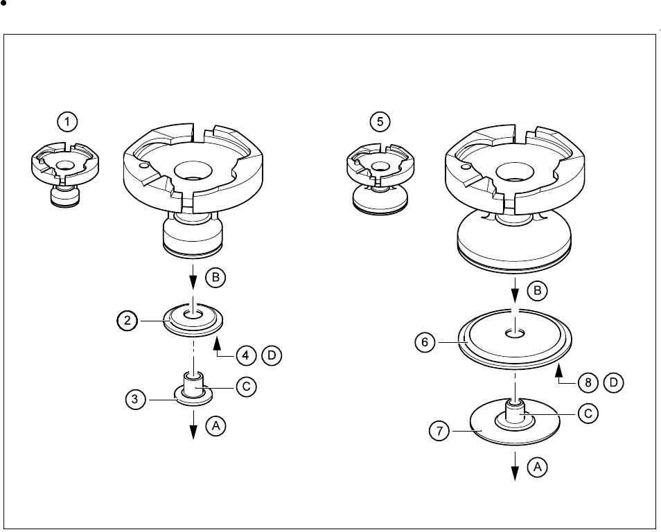
9.6.6.3 Replacing the Diaphragm of the Nozzles
Replace the diaphragm if damaged. All relevant details are shown in the following diagram.
Fig. 9.6.10 Replacing the diaphragm of the nozzles
- Key to Fig. 9.6.10
(The item numbers of the nozzles and diaphragms will be found in Section 17.2.2.)
1 Nozzle, type 418 2 Diaphragm for 418 nozzle type
3 Sleeve for 418 nozzle type 4 Supporting surface
5 Nozzle, type 419 6 Diaphragm for 419 nozzle type
7 Sleeve for 419 nozzle type 8 Supporting surface

9 Maintenance SIPLACE 80S-20/F4/F4-6/F5 User’s Manual
9.6 IC Head (SIPLACE 80F4/80F4-6/F5) Edition 03/98 from Software Version SR.404.xx
9 - 74
- Sequence of work in Fig. 9.6.10
A Pull off the sleeve.
B Remove the diaphragm.
C Clean the sleeve with alcohol and dry it before refitting.
D Rub a little talcum powder into the supporting surface of the new diaphragm and keep it absolutely
grease-free.
When you replace the sleeve, push it in as far as it will go.
9.6.6.4 Inserting Nozzles into the Nozzle Changer
After maintenance insert the nozzles by hand into their correct assigned places (by referring to the notes
you took when you removed them ) in the nozzle changer.
Insert the nozzle removal tool into each nozzle in turn and turn the nozzle anticlockwise until it locks in the
nozzle changer. Lift the tool vertically upwards and out.
Close the safety hoods and swivel doors and switch the machine on.
Have the allocations of nozzles to garage numbers displayed by making the following selection :
Gantry 1 functions → Nozzle configuration IC head
NOTE
You can only use this function when you have returned the current nozzle not by hand but, as described,
by using the Return nozzle function.
A table will be shown on the screen with the garage numbers (pick-up location numbers) and the actual
and programmed occupancies. Insert the nozzles into the nozzle changer in accordance with the ACTUAL
assignments.
Check to make sure the nozzles are properly latched.
NOTE
If the nozzles are not properly latched this will lead to errors in picking up the nozzle, while incorrectly
assigned nozzles will result in component pick-up errors.
At the start of placement the current nozzle as specified in the placement program will be picked up.
SIPLACE 80S-20/F4/F4-6/F5 User’s Manual 9 Maintenance
Edition 03/98 from Software Version SR.404.xx 9.6 IC Head (SIPLACE 80F4/80F4-6/F5)
9 - 75
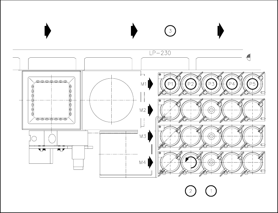
Fig. 9.6.11 Specifying the garage numbers in the nozzle changer
- Key to Fig. 9.6.11
1 Nozzle changer
2 Turn the nozzle counter-clockwise until it locks in place.
3 PCB transport direction
9.6.7 IC-Head Nozzle Survey
The nozzles setting instructions for the IC-head are given in section 17.2.2 of these operating instructions.