80S-2080F480F4-680F5 User’s Manual.pdf - 第562页
SIPLACE 80 S20/F4/F4-6/F5 User’s Manual 10 Component Handling Edition 03/98 from S oftware Version SR.404.xx 10.2 Installation - General Information 10 - 9 10.2 Instal lation - General Informatio n 10.2.1 Procedure for I…

10 Component Handling SIPLACE 80 S20/F4/F4-6/F5 User’s Manual
10.1 Overview Edition 03/98 from Software Version SR.404.xx
10 - 8
10.1.1.3 Technical Data of Bulkcase Feeders
)
Bulkcase feeder Width
Tracks
per
module
Max. number
of modules
per station
Comp.
stock
Feeder rails/ from item no.
Cycle
time
Power
supply
Base
from item no.
00142318-04
30 mm 2 2 x 20
approx.
5000
0603/045
0603/080
0805/045
0805/060
0805/085
0805/125
Mini-Melf
00142321-02
00142322-01
00142323-02
00142324-01
00142325-01
00142326-01
00142328-01
< 80 ms 30 VDC
Tab. 10.1.3 Technical data for bulkcase feeders
SIPLACE 80 S20/F4/F4-6/F5 User’s Manual 10 Component Handling
Edition 03/98 from Software Version SR.404.xx 10.2 Installation - General Information
10 - 9
10.2 Installation - General Information
10.2.1 Procedure for Installing Feeder Modules
10.2.1.1 Prepatory Work
Select the setting range for the feed module which is to be used (see vibrator configuration).
When the placement head is in the waiting position press the emergency stop button.
Open the protective covers.
Make sure that the surface where the feed module is to be located (component table) is clean and that no
components can affect the firm seating of the feed module. Information on cleaning this surface (compo-
nent table) is to be found in the chapter on maintenance (Section 9.3.3 ’Component Tables’).
10.2.1.2 Procedure
Set the feeder to the track of the component table which has been selected (see vibrator configuration).
Insert the module so that the rear side is fixed to the component table by the ball centering device, and the
front side by the corresponding centering pin. It is important that the module is placed properly on the com-
ponent table with respect to its width.
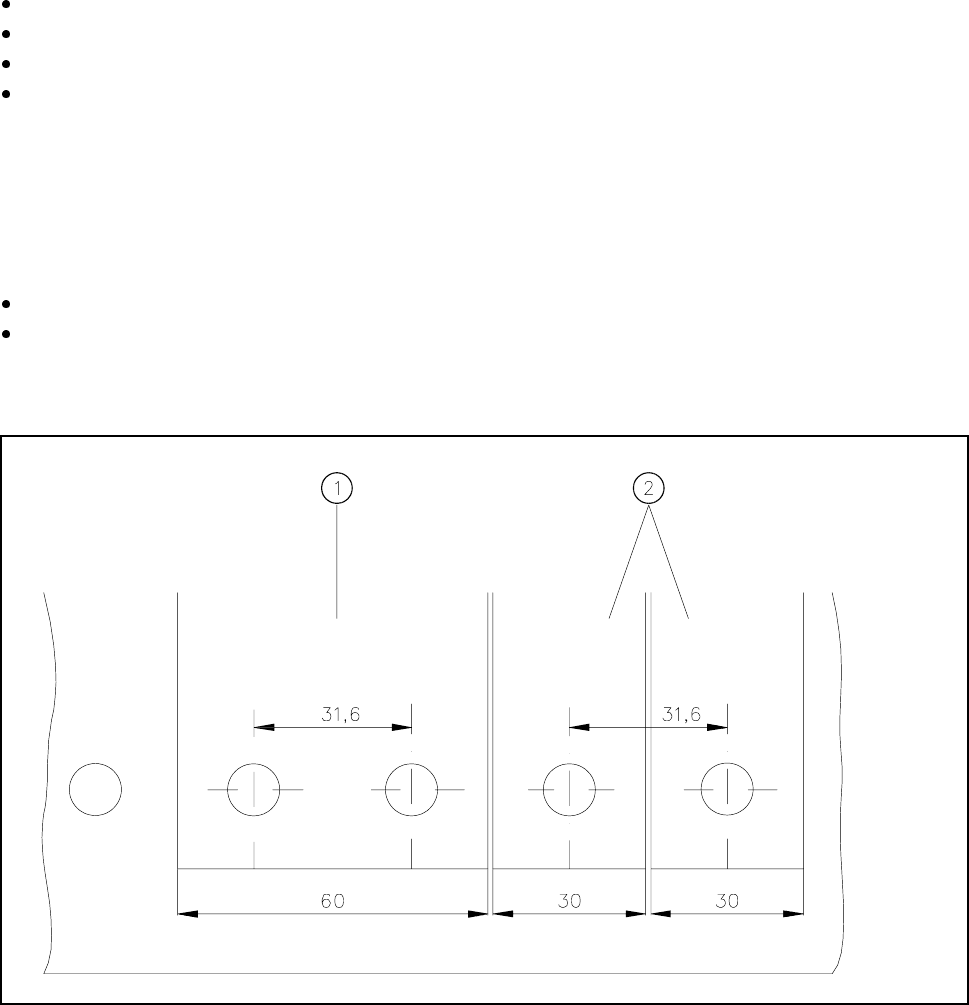
Fig. 10.2.1 Installation of modules with widths of 30 mm and 60 mm
- Key to Fig. 10.2.1
1 Feeder module with width 60 mm 2 Feeder module with width 30 mm
10 Component Handling SIPLACE 80 S20/F4/F4-6/F5 User’s Manual
10.2 Installation - General Information Edition 03/98 from Software Version SR.404.xx
10 - 10
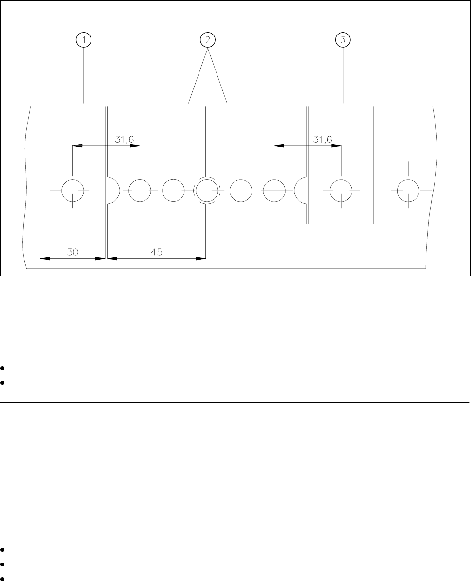
Fig. 10.2.2 Installation of modules with width 45 mm
- Key to Fig. 10.2.2
1 Feeder module width 30 mm 2 Feeder module width 45 mm
3 Feeder module width 30 mm
Make sure that the module is seated securely on the component table.
Plug the module plug into the socket which is located under the parking location
NOTE
Make sure that you do not fail to use the socket outlet which belongs to the parking location for plugging in the
module since control pulses for some modules are transmitted via this socket. If this is not observed, the
feeder may not work properly due to the wrong socket being used.
10.2.1.3 Final Activities
Close the covers and switch the control unit back on.
If applicable, perform a refill check (see Section 3.4).
Proceed with placement.