80S-2080F480F4-680F5 User’s Manual.pdf - 第564页
SIPLACE 80 S20/F4/F4-6/F5 User’s Manual 10 Component Handling Edition 03/98 from S oftware Version SR.404.xx 10.3 Component Tables 10 - 11 10.3 Comp onent Tables 10.3.1 Function The SIPLACE 80S -20/F 4 -/F 4 -6/F 5 place…
10 Component Handling SIPLACE 80 S20/F4/F4-6/F5 User’s Manual
10.2 Installation - General Information Edition 03/98 from Software Version SR.404.xx
10 - 10
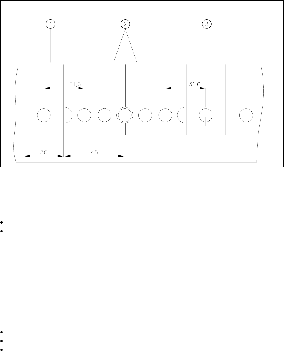
Fig. 10.2.2 Installation of modules with width 45 mm
- Key to Fig. 10.2.2
1 Feeder module width 30 mm 2 Feeder module width 45 mm
3 Feeder module width 30 mm
Make sure that the module is seated securely on the component table.
Plug the module plug into the socket which is located under the parking location
NOTE
Make sure that you do not fail to use the socket outlet which belongs to the parking location for plugging in the
module since control pulses for some modules are transmitted via this socket. If this is not observed, the
feeder may not work properly due to the wrong socket being used.
10.2.1.3 Final Activities
Close the covers and switch the control unit back on.
If applicable, perform a refill check (see Section 3.4).
Proceed with placement.
SIPLACE 80 S20/F4/F4-6/F5 User’s Manual 10 Component Handling
Edition 03/98 from Software Version SR.404.xx 10.3 Component Tables
10 - 11
10.3 Component Tables
10.3.1 Function
The SIPLACE 80S-20/F
4
-/F
4
-6/F
5
placement machines are equipped with changeable component tables.
These component tables can be changed with relatively little effort.
10.3.2 Changing Component Tables
10.3.2.1 Tools Required
10.3.2.2 Removal
WARNING
When you change the component table, always follow the sequence for removing the plugs from the commu-
nication unit and then connecting them again as described below. If you do not follow the specified order,
faults may occur in the component table.
WARNING
Move the portal out of the range of the component table over the PCB transport. This will prevent the possibil-
ity of a head crash.
DANGER
Press the emergency stop button. The gantry axes are switched off and isolated.
This will prevent the gantries starting up accidentally, thus preventing the associated risk of injury or damage.
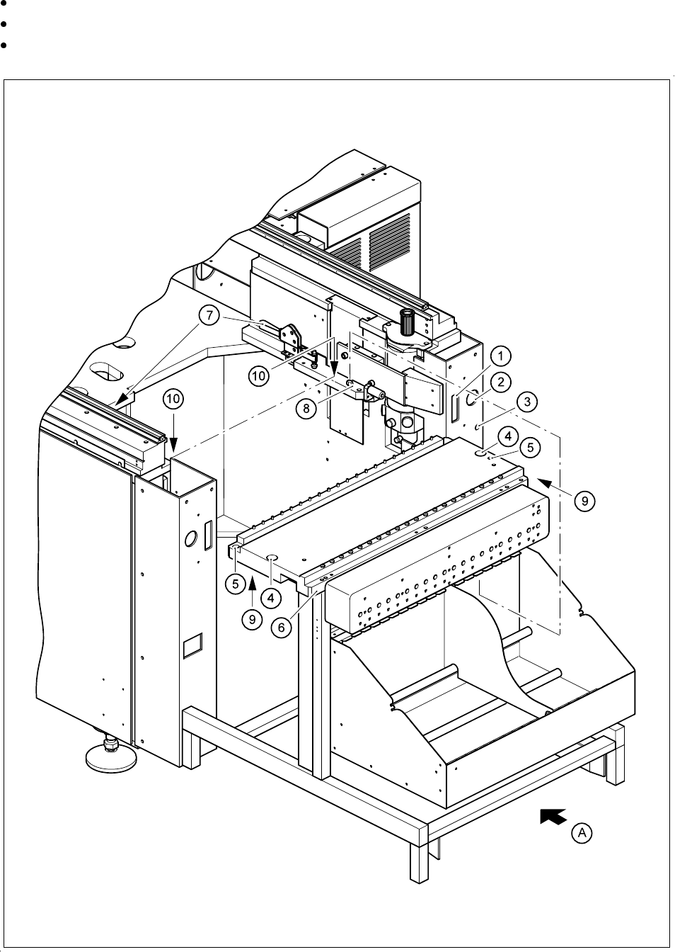
Remove the plugs from the power supply for the component table.2.
Remove the communication plug 1.
If necessary, remove the connector for the compressed air supply to the component table 3.
Push the platform truck under the component table (A).
Loosen the two hexagon socket head screws for fixing the component table 5.
From item number
Hexagon socket spanner, set
Component table platform truck 00123141-01
10 Component Handling SIPLACE 80 S20/F4/F4-6/F5 User’s Manual
10.3 Component Tables Edition 03/98 from Software Version SR.404.xx
10 - 12
Open the horizontal tensioner 7.
Carefully raise the component table using the platform truck until the centering pins
«
are outside the hole
s.
Then pull out the component table.
Fig. 10.3.1 Removal of the component table