80S-2080F480F4-680F5 User’s Manual.pdf - 第567页
10 Component Handling SIPLACE 80 S20/F4/F4-6/F 5 User’s Manual 10.3 Component Tables Edition 03/98 from Software Version SR.404.xx 10 - 14

SIPLACE 80 S20/F4/F4-6/F5 User’s Manual 10 Component Handling
Edition 03/98 from Software Version SR.404.xx 10.3 Component Tables
10 - 13
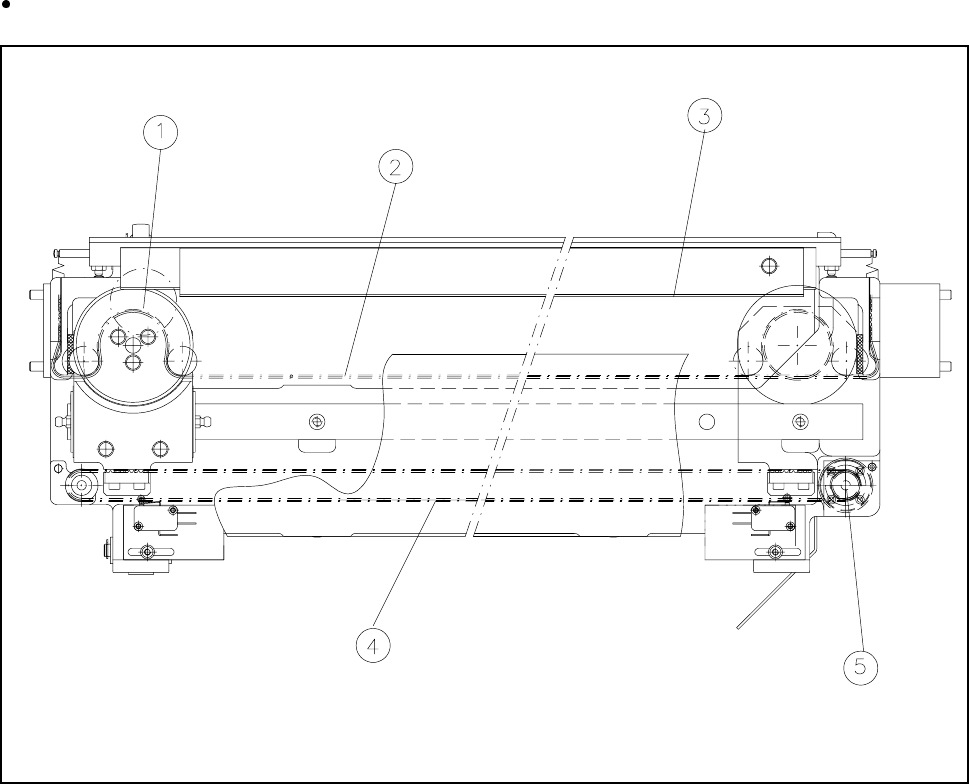
- Key to Fig. 10.3.1
10.3.2.3 Installation
Make sure that the contact surfaces of the component table and machine are clean (
9
and 10).
Pick up a component table with the lifting truck and raise the component table until it will not catch any-
where while being slid into the machine.
Carefully push the component table into the machine until the centering pin locating holes on the compo-
nent table are above the centering pins (4 and 8).
Carefully lower the component table until the component table rests on the machine base mounting.
Close the clamping levers (7).
Then plug in the flat plug for the communication signals.
Insert and tighten the two hexagon socket head screws
5
.
Plug in the round power supply plug.
Close the protective covers.
Release the EMERGENCY-STOP button.
1
Connection for the communication interface
2 Connection for the power supply to the component table
3
Compressed air connection
4
Holes for the centering pins
5 Hexagon socket head screws for fixing the component table
6
Supporting surface for the component table
7
Horizontal tensioner
8
Centering pins
9 Contact surfaces for the component table
10 Contact surfaces for the machines
A Push in the component table platform truck
10 Component Handling SIPLACE 80 S20/F4/F4-6/F5 User’s Manual
10.3 Component Tables Edition 03/98 from Software Version SR.404.xx
10 - 14
SIPLACE 80 S20/F4/F4-6/F5 User’s Manual 10 Component Handling
Edition 03/98 from Software Version SR.404.xx 10.4 Empty Tape Cutter on SIPLACE 80S-20/F4/F4-6 Automatic Placement Machines
10 - 15
10.4 Empty Tape Cutter on SIPLACE 80S-20/F
4
/F
4
-6
Automatic Placement Machines
10.4.1 General
The SIPLACE 80S-20/F
4
automatic placement system is equipped with an empty tape cutter at the installa-
tion locations for the two component tables. The empty tape cutter cuts up the waste tape.
The cut pieces of tape drop into the tape container beneath the component table.
Empty the tape container on a daily basis.
Fig. 10.4.1 Tape cutter
- Key to Fig. 10.4.1
1 Cutter wheel 2 Toothed belt for cutter wheel
3 Cutting edge 4 Drive belt
5 Drive motor