80S-2080F480F4-680F5 User’s Manual.pdf - 第572页
SIPLACE 80 S20/F4/F4-6/F5 User’s Manual 10 Component Handling Edition 03/98 from S oftware Version SR.404.xx 10.6 Wafflepack Changer 10 - 19 10.6 Wafflepack Changer 10.6.1 Overview Fig. 10.6.1 Wafflepack changer on SIPLA…
10 Component Handling SIPLACE 80 S20/F4/F4-6/F5 User’s Manual
10.5 Reel Container (New Group) Edition 03/98 from Software Version SR.404.xx
10 - 18
NOTE
PLEASE NOTE
With large tape reels (> 5"), use insertion spindles to ensure that the conveyors operate reliably.
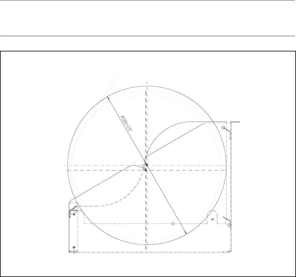
Fig. 10.5.2 Reel container - side view (reel inserted)
SIPLACE 80 S20/F4/F4-6/F5 User’s Manual 10 Component Handling
Edition 03/98 from Software Version SR.404.xx 10.6 Wafflepack Changer
10 - 19
10.6 Wafflepack Changer
10.6.1 Overview
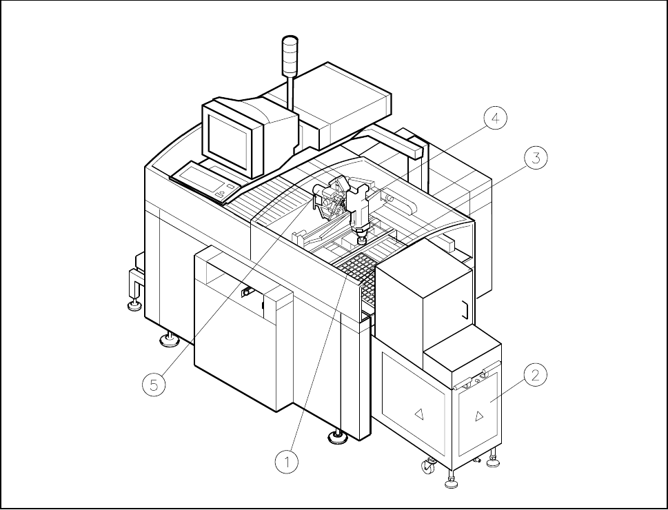
Fig. 10.6.1 Wafflepack changer on SIPLACE 80F
4
- Key to Fig. 10.6.1
1 Wafflepack changer on location 1 2 Wafflepack changer
3 Location 2 4 IC placement head
5 Revolver head

10 Component Handling SIPLACE 80 S20/F4/F4-6/F5 User’s Manual
10.6 Wafflepack Changer Edition 03/98 from Software Version SR.404.xx
10 - 20
10.6.2 General Information
The use of flatpack ICs is gaining more and more importance in the manufacture of printed circuit boards.
These components have now reached the point where they are almost always delivered on trays (wafflepack
magazines).
The space taken up by magazine trays is however relatively high when compared with the component den-
sity. In addition, due to their low holding capacity, the wafflepack magazines must frequently be changed and
if this has to be done by hand this necessarily involves interrupting the placement process.
But when a wafflepack changer is used there is no time lost unnecessarily in the storing and automatic chang-
ing of the wafflepack magazines. Programmed access to up to 28 freely selectable wafflepack magazines
also increases the range of available components.
NOTE
The wafflepack changer is located on the lefthand side of the SIPLACE 80 F table.
The wafflepack changer does not require the entire width of the component table. On this side of the table
10 locations remain free which can be used for the 20 x 8 mm tape module, for example.