80S-2080F480F4-680F5 User’s Manual.pdf - 第576页
SIPLACE 80 S20/F4/F4-6/F5 User’s Manual 10 Component Handling Edition 03/98 from S oftware Version SR.404.xx 10.6 Wafflepack Changer 10 - 23 added to t he set-up . The wafflep ack cha nger is defi ned as Lo cation 1. In …
10 Component Handling SIPLACE 80 S20/F4/F4-6/F5 User’s Manual
10.6 Wafflepack Changer Edition 03/98 from Software Version SR.404.xx
10 - 22
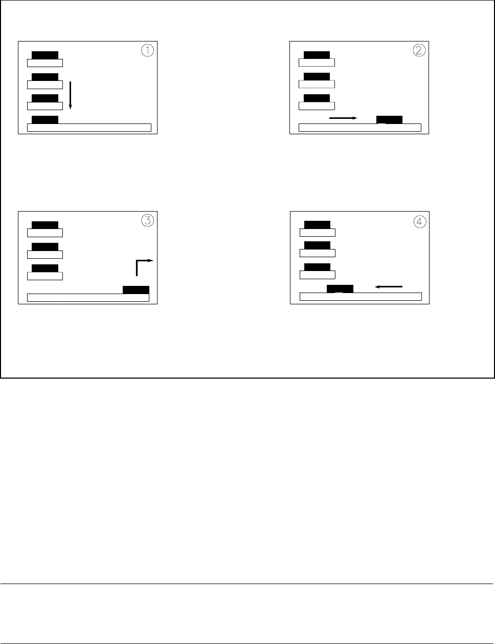
Fig. 10.6.3 Functional sequence
- Key to Fig. 10.6.3
1 The selected level of the magazine storage unit is positioned on the feeder axis (horizontal).
2 The tray is transferred to the access area of the placement head.
3 The components are removed.
4 The tray is returned again.
- The lift in the magazine storage unit brings the tray from the selected level into position on the horizontal
feeder axis.
- The tray with the flatpack magazine is brought into the placement head’s access area.
- Once the desired components have been removed by the placement head, the magazine is returned in the
reverse sequence of operations.
NOTE
If the placement sequence is interrupted with the wafflepack changer being switched off, the set-up and the
current fill level will remain saved in memory.
- If the placement sequence is restarted using the set-up which was being used when the sequence was
aborted, the placement machine will be able to pick up the next component from the point where it picked
up the previous one.
- The position of the trays in the flatpack magazine storage unit and the components they are filled with is
SIPLACE 80 S20/F4/F4-6/F5 User’s Manual 10 Component Handling
Edition 03/98 from Software Version SR.404.xx 10.6 Wafflepack Changer
10 - 23
added to the set-up. The wafflepack changer is defined as Location 1. In this connection see UNIX line
computer user manual, under ’Station editor’.
10.6.4 Inserting the Trays
The trays are monitored to make sure they are in the correct position in the magazine storage
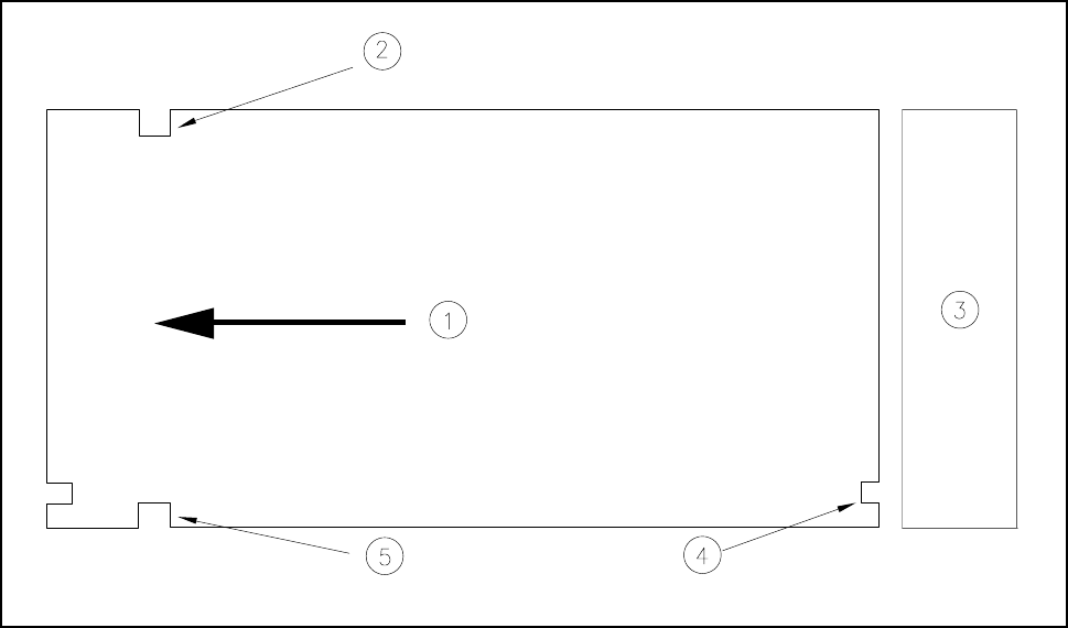
Fig. 10.6.4 Position of the trays - viewed from the top
- Key to Fig. 10.6.4
1 Transport direction 2 Driver notch
3 Magazine storage unit 4 Check notch
5 Driver notch
It should be noted here that the driver notches in the magazine carriers are inserted forwards with respect to
the direction of transport (see Fig. 10.6.4). The check notches of the individual magazine carriers must be
positioned one above the other and point in the direction of the magazine storage unit.

10 Component Handling SIPLACE 80 S20/F4/F4-6/F5 User’s Manual
10.6 Wafflepack Changer Edition 03/98 from Software Version SR.404.xx
10 - 24
10.6.5 Display and Operating Elements
The wafflepack changer has an EMERGENCY STOP switch and a switch for changing the speed. These two
control elements are located on the machine base at the rear of the wafflepack changer.
l Key - slow
With flatpack magazines carrying small components which could fall out of their pockets if the flatpack
magazine moves quickly, it is possible to reduce the speed for the flatpack magazine.
Press the Slow key.
All flatpack magazines will now travel at a slower speed.
l Switch - EMERGENCY-STOP
Press the EMERGENCY STOP switch. The power supply will be switched off and the entire system shut
down.
10.6.6 Safety Devices
l Switch - EMERGENCY-STOP
The entire system with, for example, SIPLACE 80F and wafflepack changer is immediately stopped. At this
point placement can be continued or aborted. Make sure that all boards have been completely assembled.
l Safety panel
Once the safety panels are opened the wafflepack changer is switched into a de-energized state and the
wafflepack changer’s operational sequence stopped. Upon the safety panel being closed the wafflepack
changer resumes operations.
CAUTION
The wafflepack changer safety door should not be opened while a component is being picked up from the
wafflepack changer.