80S-2080F480F4-680F5 User’s Manual.pdf - 第622页
SIPLACE 80S-20/F4/F4-6/F5 User’s Manual 11 Station Extensions/Options Edition 03/98 from Software Version SR.404.xx 11.5 Flip-Chip Vision Module 11 - 25 11.5 Flip-Chip Vision Module 11.5.1 Overview The flip c hip visio n…

11 Station Extensions/Options SIPLACE 80S-20/F4/F4-6/F5 User’s Manual
11.4 Component Barcode Edition 03/98 from Software Version SR.404.xx
11 - 24
l Alternative if barcode cannot be read-in:
- Switch out refill check in the machine options.
- Enter bar code by hand.
11.4.3 Operating
NOTE
In this connection see also Section 3.2, ’Set-Up’ and 3.4, ’Feeders’ in this user's manual.
In the Set-up menu select the view Empty tracks.
Use the bar code reader to read the track bar code in question.
If the track is included in the set-up and the component has a bar code, the Set-up check with bar code
dialog will appear, showing the corresponding track.
NOTE
You can open this dialog by clicking on the track in question and then on the Set-up check with bar code
button.
Following a successful check and subsequent reading-in of the return barcode, the track can be refilled.
11.4.4 Technical Data
Component barcode
Max. resolution 0.13 mm
Reading speed 36 scans/sec
Laser class IEC Class 2
Degree of protection IP 64
Readable barcode types Code 39 (normal / FULL ASCII)
EAN/UPC (family with/without ADD ON
CODABAR
INTERLEAVED 2/5
NORMAL 2/5 (5 bars)
(other types available upon request)
SIPLACE 80S-20/F4/F4-6/F5 User’s Manual 11 Station Extensions/Options
Edition 03/98 from Software Version SR.404.xx 11.5 Flip-Chip Vision Module
11 - 25
11.5 Flip-Chip Vision Module
11.5.1 Overview
The flip chip vision module is based on the concept of the fine pitch vision system.
It differs from it in that the resolution is higher and the illumination has been modified. Two illumination levels
are available, for a flat and for a middle angle of incidence.
The package form editor has been extended to cover programming of the array-type lead structures and for
some irregular structures.
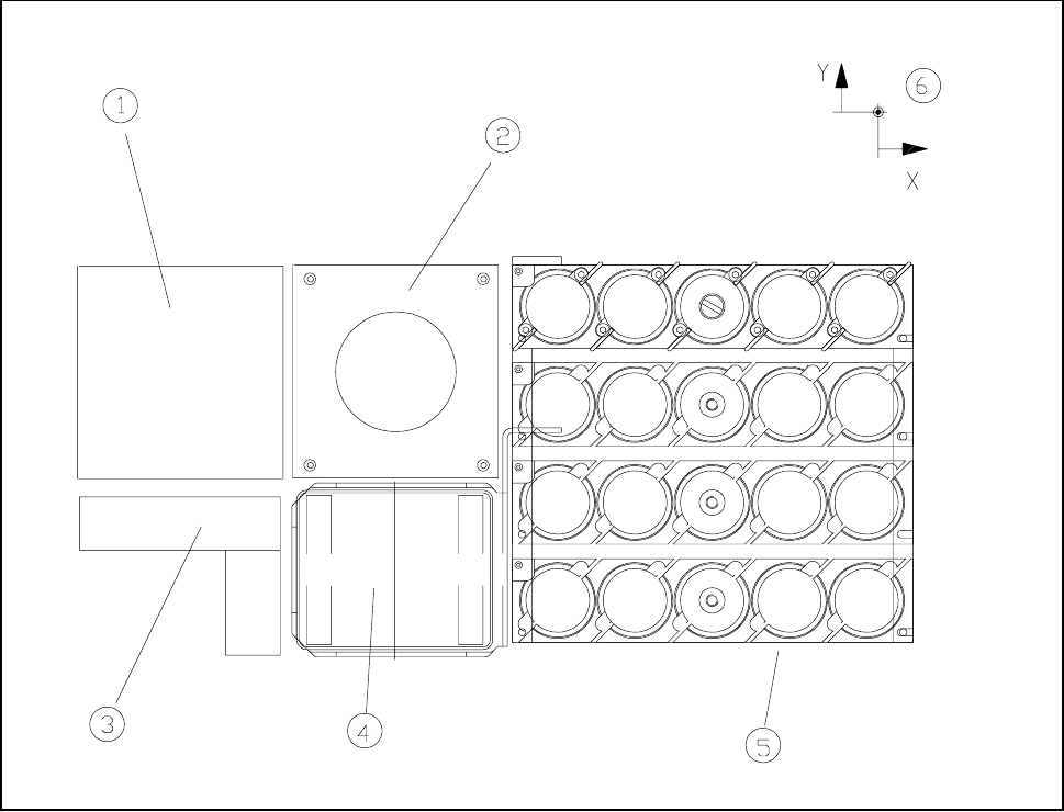
Fig. 11.5.1 Location of the flip chip vision module
- Key to Fig. 11.5.1
1 Fine-pitch vision module 2 Flip-chip vision module
3 Coplanarity laser module 4 Reject box
5 Nozzle changer 6 Machine zero point
The module is described, including using it, in Chapter 5 ’Vision Functions’.
11 Station Extensions/Options SIPLACE 80S-20/F4/F4-6/F5 User’s Manual
11.5 Flip-Chip Vision Module Edition 03/98 from Software Version SR.404.xx
11 - 26
11.5.2 Safety Information concerning the Components Vision Systems
in the 80F Machine
DANGER
No work may be carried out or modifications made to the safety equipment of 80F automatic placement
systems or the IC or flip-chip module.
The optical range of the IC and flip-chip camera conforms to laser class 1, provided that the camera is perma-
nently fixed in the automatic placement system and that the protective covers are closed (EN 60825-1 and
IEC 825).
Fig. 11.5.2 Identification label for Laser class 1
LASER CLASS 1