80S-2080F480F4-680F5 User’s Manual.pdf - 第639页
11 Station Extensions/Options SIPLACE 80S-20/F4/F4-6/F5 User’s M anual 11.7 Dispenser Flux Application Unit for S IPLACE 80F4/F4-6/F5 Edition 03/98 from S oftware Version SR.404.xx 11 - 42 11.7.6 User Interface NOTE For …

SIPLACE 80S-20/F4/F4-6/F5 User’s Manual 11 Station Extensions/Options
Edition 03/98 from Software Version SR.404.xx 11.7 Dispenser Flux Application Unit for SIPLACE 80F4/F4-6/F5
11 - 41
Loosen the 4 fixing screws for the rear cover of the flux application unit and then remove the cover.
Loosen the two fixing screw in the slots.
Push the piston down and adjust the flux application unit so that the distance between the tip of the dis-
pensing needle and the PCB is 1 mm.
Push the flux application unit against the lateral stop and tighten the fixing screws.
Fit the rear cover.
11 Station Extensions/Options SIPLACE 80S-20/F4/F4-6/F5 User’s Manual
11.7 Dispenser Flux Application Unit for SIPLACE 80F4/F4-6/F5 Edition 03/98 from Software Version SR.404.xx
11 - 42
11.7.6 User Interface
NOTE
For the flip-chip component to be assembled and provided with flux, a placement program with flip-chip com-
ponents must be written in the line computer and sent to the station computer. See the UNIX user‘s manual.
The Fluxing option must be activated under Machine options in the station computer. See Section 2.4.4,
’The Options Menu’ of the SIPLACE 80S-20/F
4
/F
4
-6/F
5
user‘s manual.
11.7.6.1 Package Form List and Parameters
In order to apply flux to a board for the purpose of placing flip chips, at the station computer you must add the
process data to a list and also enter general parameters regarding fluxing.
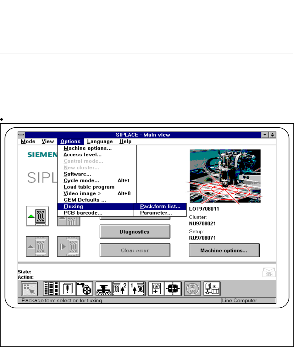
Select the submenu Fluxing in the Options menu.
Fig. 11.7.6 Fluxing option
F
SIPLACE 80S-20/F4/F4-6/F5 User’s Manual 11 Station Extensions/Options
Edition 03/98 from Software Version SR.404.xx 11.7 Dispenser Flux Application Unit for SIPLACE 80F4/F4-6/F5
11 - 43
11.7.6.2 Editing the Package Form List
To be able to edit data for the flip-chip component which is to be placed, select the Package form list
menu.
In this menu you can add flip-chip components, each with its own GF No.[package form number] and also
edit them. See Fig. 11.7.7 and Fig. 11.7.8.
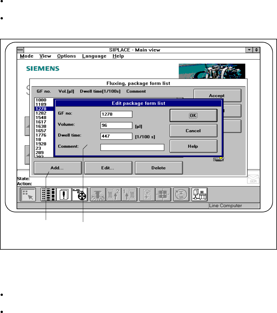
Fig. 11.7.7 Fluxing, package form list
- Key to Fig. 11.7.7
1 Add button 2 Input fields
Click on the Add button to describe a new component for fluxing and then enter the corresponding data
into the input fields.
You will need to enter the following data:
GF no.:
- The package form number of the component in question.
- You can input package form numbers between 1 and 32000.
F
2 1