80S-2080F480F4-680F5 User’s Manual.pdf - 第69页
SIPLACE 80S-20/F4/F4-6/F5 User’s Manual 1 Operational Safety Edition 03/98 f rom SW SR.404.xx 1.6 Lock out and tag out procedure when performing any maintenance work or service work 1 - 27 1.6 Lock out and tag out pro ce…
1 Operational Safety SIPLACE 80S-20/F4/F4-6/F5 User’s Manual
1.5 Energy state of automatic placement systems after switching off at the main switch Edition 03/98 from SW SR.404.xx
1 - 26
1.5.1 Placement system switched off at the main switch, but still con-
nected to the mains
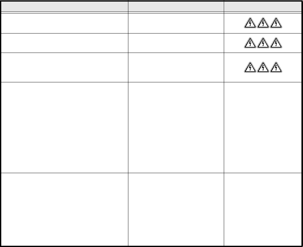
The following table specifies the voltages of assemblies when the automatic placement system is switched off
at the main switch, but still connected to the mains supply.
1.5.2 Placement system switched off at the main switch and discon-
nected from the mains
The automatic placement system is unpowered, apart from slight residual voltages in the servo unit.
1.5.3 Compressed air conditions in the automatic placement system
after switching off at the main switch
When the system is switched off at the main switch (item 1 in Fig. 1.5.1) or if the power supply fails, the elec-
trically-controlled main valve Y1 of the compressed air unit closes (Fig. 1.4.1, page 1 - 23). The pressure will
drop to 0 bar within 5 seconds.
Assembly Voltage
Mains filter Z1
Terminals L1, L2, L3
3 x 400 VAC
Service socket
230 VAC
Main switch Q1
Terminals 1, 3, 5
Terminals 2, 4, 6
3 x 400 VAC
0 VAC
Servo unit (see item 7 in Fig. 1.5.1)
Test socket 001
Test socket 002
Test socket 003
Test socket 004
Test socket 005
Test socket 006
Test socket 008
Test socket 009
GND 007
< 12 VDC
< 12 VDC
< 12 VDC
0 VDC
0 VDC
0 VDC
< 12 VDC
< 12 VDC
Control unit (see item 6 in Fig. 1.5.1)
Test socket 5 V
Test socket + 12 V
Test socket – 12 V
Test socket + 15 V
Test socket – 15 V
Test socket + 24 V
GND
0 VDC
0 VDC
0 VDC
0 VDC
0 VDC
0 VDC
Tab. 1.5 - 1 Voltages of assemblies when the automatic placement system is switched off at the main switch,
but still connected to the main power
SIPLACE 80S-20/F4/F4-6/F5 User’s Manual 1 Operational Safety
Edition 03/98 from SW SR.404.xx 1.6 Lock out and tag out procedure when performing any maintenance work or service work
1 - 27
1.6 Lock out and tag out procedure when performing any
maintenance work or service work
1.6.1 Purpose and scope
Before performing any maintenance work or service work, a procedure of locking and tagging must be fol-
lowed. The procedure, when followed correctly eliminates the possibility of an employee being injured.
1.6.2 Description
Whenever it becomes necessary to isolate, control and release energy, the following procedure is to be fol-
lowed:
1. Notify affected employees.
2. Shut down equipment, using normal stopping procedures, such as
- depressing the stop button
- shutting down the station computer
- switching off the placement system at the main switch or
- opening the toggle switch.
3. Isolate the equipment from all its energy sources such as
– compressed air supply and
– power supply.
4. Lock Out equipment.
– Apply the lock and the lockout whenever possible.
–
The Tag Out alternative:
If a machine can be locked out, it must be. However, there are situations where energy isolating
devices can not accommodate locks. In these cases, the energy isolating devices must be tagged to
warn employees that the machine is de-energized for servicing. The tag must be securely fastened, it
must be placed in a position visible to all and it may only be removed by the person who attached it.
5. Relieve stored energy
Stored energy in the compressed air supply or electrical energy in electrolytic capacitors must be released
by appropriate means.
– After switching off the placement machine wait until the voltages and the compressed air have dis-
charged as specified in sections 1.3 and 1.4 to be able work without any risk.
6. Verify the lock out.
– Testing the lock out can be done simply by pressing the start button.
7. The following steps must be taken to restore the machine to operation.
8. Check the area, authorized employees should remove all of their tools and reinstall all guards.
9. Notify all affected employees.
1 Operational Safety SIPLACE 80S-20/F4/F4-6/F5 User’s Manual
1.6 Lock out and tag out procedure when performing any maintenance work or service work Edition 03/98 from SW SR.404.xx
1 - 28
Before removing even one lock or tag, inform all workers in the area that the machine is going to be
restarted.
10. Remove locks/tags.
Each authorized employee must remove his or her own lock. Each authorized employee will have his or
her own lock.
11. Turn the machine on. Authorized workers should observe the equipment in operation to insure repairs
were done correctly.
1.6.3 Testing
The maintenance or electrical person may test the circuits by energizing the circuit for a short period of time
without voiding the lock out procedure provided. This may be done only when no other work is being per-
formed by any other person on the equipment being tested.
It is extremely important that all remote start switches be tagged with the “Do Not Operate” tag to prevent
inadvertent operation of the equipment during these periods.
1.6.4 Responsibilities
1. It shall be the responsibility of the maintenance and electrical personnel to make sure this procedure is
adhered to.
2. It shall be the responsibility of the maintenance and electrical personnel’s immediate supervisor to instruct
his personnel on this procedure.
3. It shall be the responsibility of the Safety Officer with assistance from the Safety Committee, Health Ser-
vice Department, and the various managers and Vice-Presidents to administer the Lock Out / Tag Out
Procedure.
1.6.5 Training
1. Employee training
The safety regulations require training for every individual, of course every employee is not exposed to the
same degree of danger or is involved with LO/TO as others are. So extensive training is not necessary for
everyone.
2. To determine how much training to provide for each worker, the employees are divided into three groups.
Each group has its own level of training.
3. Authorized employees.
These workers actually install the locks and tags and do the maintenance or service work. So they must
know the most about controlled energy. First, they must be able to recognize all energy sources and mea-
sure the amount of energy. Authorized employees must look for energy sources out of the realm of the
obvious. These energy sources include electrical, mechanical, hydraulic, pneumatic, chemical, thermal
and gravitational. Once these workers can recognize all energy sources they must be taught how to iso-