80S-2080F480F4-680F5 User’s Manual.pdf - 第706页
SIPLACE 80S-20/F4/F4-6/F5 User’s Manual 17 Nozz le Overview Edition 03/98 from Software Version SR.404.xx 17.1 Nozzle Contour Diagrams 17 - 5 17.1.1.3 Nozzle and Nozzle Contour Fig. 17.1.3 ’Representation o f the nozz le…
17 Nozzle Overview SIPLACE 80S-20/F4/F4-6/F5 User’s Manual
17.1 Nozzle Contour Diagrams Edition 03/98 from Software Version SR.404.xx
17 - 4
17.1.1.2 Long and Narrow Sides of the Nozzle
For every nozzle type (for example, 7xx) there are two nozzle contour diagrams. One diagram for the long
side and one diagram for the narrow side of the nozzles. A general view of the nozzle side in question is pro-
vided in Fig. 17.1.2 ’Top view of the nozzle’.
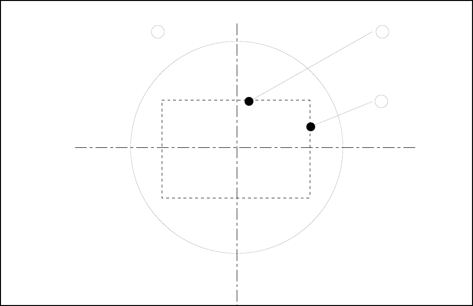
Fig. 17.1.2 Top view of the nozzle
- Key to Fig. 17.1.2
1 Top view of the nozzle 2 Long side of the nozzle
3 Narrow side of the nozzle
2
3
1
SIPLACE 80S-20/F4/F4-6/F5 User’s Manual 17 Nozzle Overview
Edition 03/98 from Software Version SR.404.xx 17.1 Nozzle Contour Diagrams
17 - 5
17.1.1.3 Nozzle and Nozzle Contour
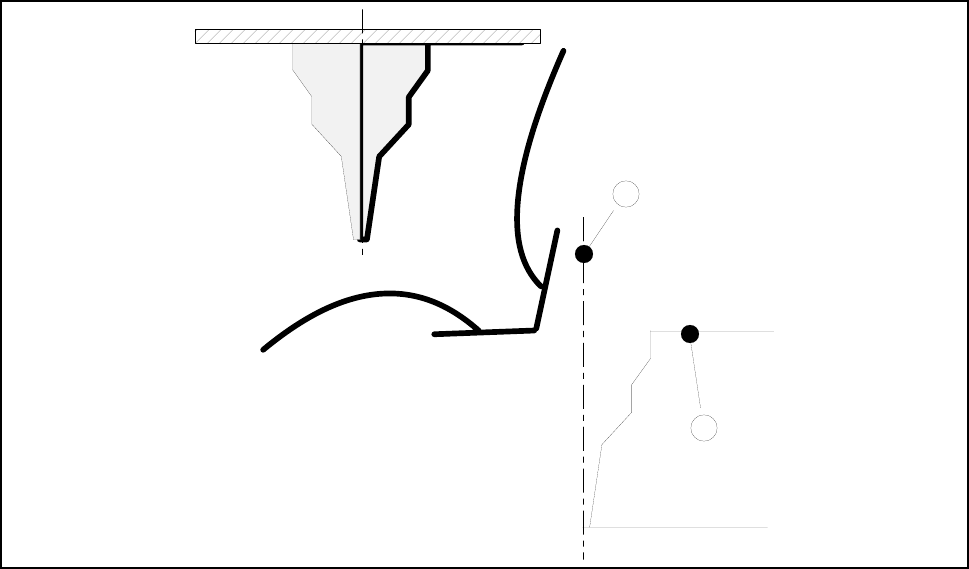
Fig. 17.1.3 ’Representation of the nozzle contour (right-hand half of the nozzle)’ shows the relation between
the nozzle and the diagram.
The contour of the nozzle is depicted in the nozzle contour diagram.
Fig. 17.1.3 Representation of the nozzle contour (right-hand half of the nozzle)
- Key to Fig. 17.1.3
1 Center of the nozzle 2 Nozzle contour
1
2
17 Nozzle Overview SIPLACE 80S-20/F4/F4-6/F5 User’s Manual
17.1 Nozzle Contour Diagrams Edition 03/98 from Software Version SR.404.xx
17 - 6
17.1.2 Representation of a Nozzle Contour Diagram
You can obtain the following information from a nozzle contour diagram:
- Placement shadow in [mm]
- Components height difference in [mm]
NOTE
The placement shadow is defined as the distance required between two components when they are
inserted and taking the height difference into account.
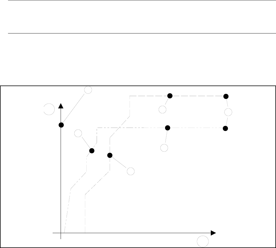
A nozzle contour diagram depicts all of the nozzle contours of a nozzle type.
As an example, Fig. 17.1.4 ’Representation of multiple nozzle contour diagrams’ shows two nozzle contours in
one diagram.
Fig. 17.1.4 Representation of multiple nozzle contour diagrams
- Key to Fig. 17.1.4
1 Components height difference in [mm] 2 Placement shadow in [mm]
3 Center of nozzle 4 Nozzle contour of nozzle B
5 Nozzle contour of nozzle A 6 Encoder disk of nozzle B
7 Encoder disk of nozzle A 8 Outside edge of encoder disk
A correlation between the components height difference and the placement shadow can be derived from
these values (see Fig. 17.1.5 ’Correlation between components height difference and placement shadow’).
4
1
3
7
6
8
5
2