80S-2080F480F4-680F5 User’s Manual.pdf - 第710页
SIPLACE 80S-20/F4/F4-6/F5 User’s Manual 17 Nozz le Overview Edition 03/98 from Software Version SR.404.xx 17.1 Nozzle Contour Diagrams 17 - 9 Fig. 17.1.6 Nozzle contour for nozzle type 7xx / ceramic / narrow side - Key t…

17 Nozzle Overview SIPLACE 80S-20/F4/F4-6/F5 User’s Manual
17.1 Nozzle Contour Diagrams Edition 03/98 from Software Version SR.404.xx
17 - 8
17.1.3 Nozzle Contour Diagrams
Diagrams 17.1.6 to 17.1.12 contain the nozzle contour diagrams for the narrow and wide sides of each nozzle
type.
Nozzle type Contour diagram
narrow side
Contour diagram
long side
70x Vectra / ceramic Fig. 17.1.6 Fig. 17.1.7
71x, 72x Vectra C130 Fig. 17.1.8 Fig. 17.1.9
75x Vectra / polyurethane,
ESD-conductive
Fig. 17.1.10 Fig. 17.1.11
8xx Vectra C130 / Evoprene Fig. 17.1.12
SIPLACE 80S-20/F4/F4-6/F5 User’s Manual 17 Nozzle Overview
Edition 03/98 from Software Version SR.404.xx 17.1 Nozzle Contour Diagrams
17 - 9
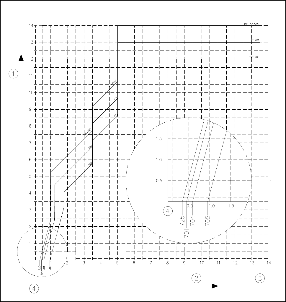
Fig. 17.1.6 Nozzle contour for nozzle type 7xx / ceramic / narrow side
- Key to Fig. 17.1.6
1 Components height difference [mm] 2 Placement shadow [mm]
3 Outer edge of encoder disk 4 Center of nozzle
17 Nozzle Overview SIPLACE 80S-20/F4/F4-6/F5 User’s Manual
17.1 Nozzle Contour Diagrams Edition 03/98 from Software Version SR.404.xx
17 - 10
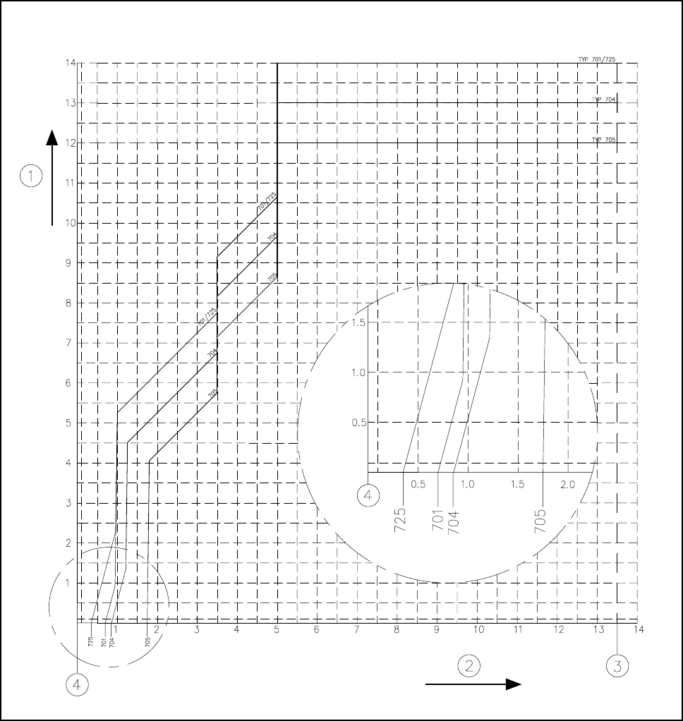
Fig. 17.1.7 Nozzle contour for nozzle type 7xx / ceramic / long side
- Key to Fig. 17.1.7
1 Components height difference [mm] 2 Placement shadow [mm]
3 Outer edge of encoder disk 4 Center of nozzle