SussPA300UserGuide - 第13页
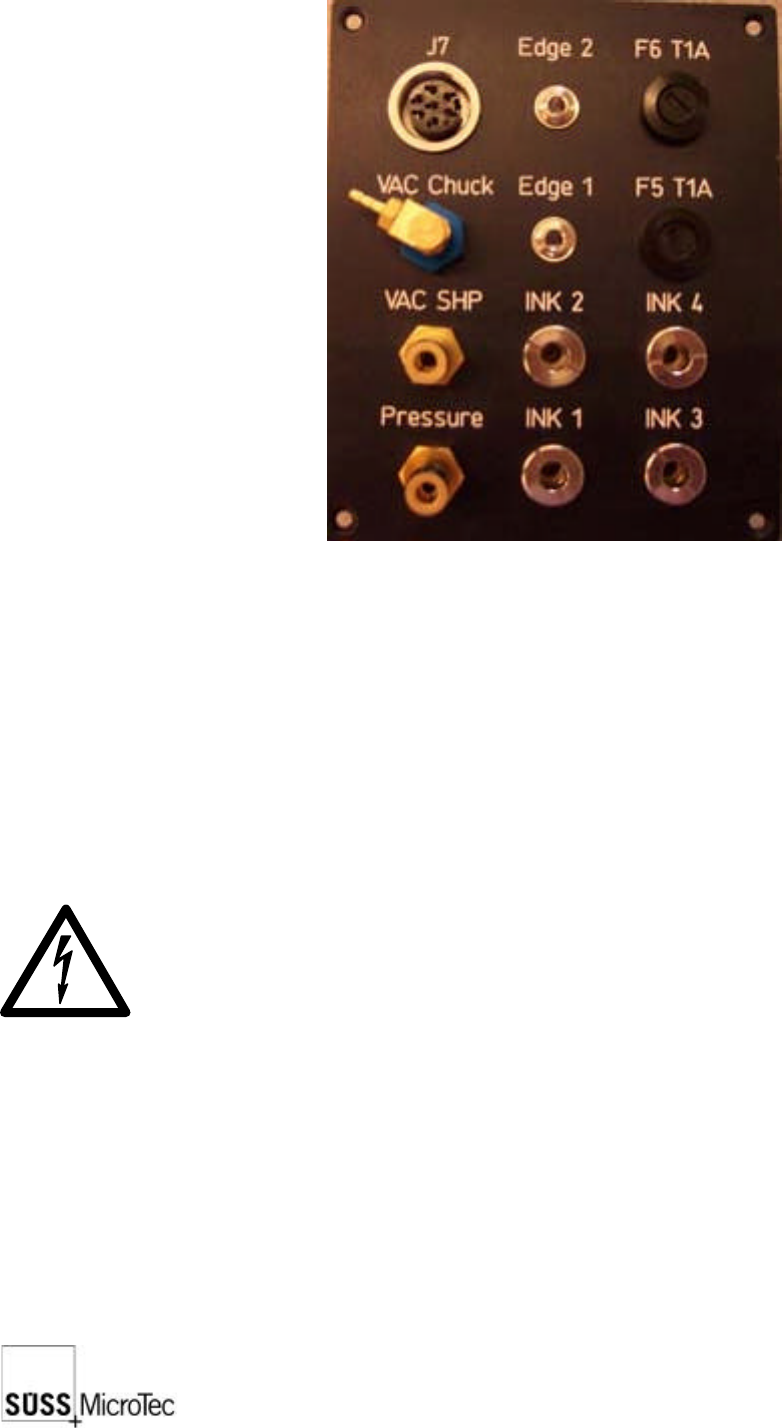
12 SUSS / PA300 / User Manual / M10-121841-00 / February 2002 2.11 Utility Distribution Exits: VAC CHUCK: Vacuum exit for the chuck VAC SHP: Vacuum exit for the probe head platen INK 1...INK4: 4 Inker exits (each roughly…
SUSS / PA300 / User Manual / M10-121841-00 / February 2002
11
Main microc
o
n
t
r
o
l
l
e
r
b
o
a
r
d
Misc. Outpu
t
i
n
t
e
r
f
a
c
e
c
a
r
d
(
C
4
)
Main fuses
(
F
1
/
F
2
)
Functional G
r
o
u
n
d
T
e
r
m
i
n
a
l
s
Main power
s
u
p
p
l
y
Motorized P
r
o
b
e
H
e
a
d
s
(
1
e
a
c
h
)
Control (end
l
i
m
i
t
s
,
e
n
c
o
d
e
r
signals, LED
s
)
ControlBox
i
n
t
e
r
f
a
c
e
Reserve so
c
k
e
t
s
f
o
r
m
o
t
o
r
i
z
e
d
t
u
r
r
e
t
/
options i.e.:
A
u
t
o
m
a
t
i
c
p
r
o
b
e
r
i
n
p
u
t
s
Power supp
l
y
s
o
c
k
e
t
s
(
x
3
)
IEEE
Prober conn
e
c
t
i
o
n
s
Address Sw
i
t
c
h
Extractor fa
n
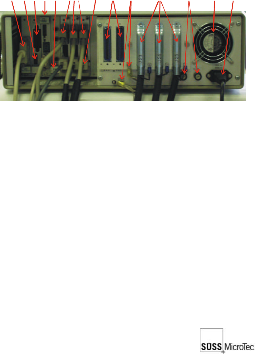
Electronics Rack: (see above)
Mains cable (3 prong)
3 electrical control cables to the probe station (plus 2 spare)
Ground terminal to the probe station
Probe Station:
Inputs (on the rear side on the right of double side probe machines and on the right
hand side at the back of standard machines)
3 electrical control cables to the electronics rack
1 vacuum inlet
1 compressed air inlet
Cover switch (interlock function)
Chuck potential; max. 120 VDC (isolated from system)
System potential; one additional on base frame on left hand side of bridge.
12
SUSS / PA300 / User Manual / M10-121841-00 / February 2002
2.11 Utility Distribution
Exits:
VAC CHUCK: Vacuum exit for the chuck
VAC SHP: Vacuum exit for the probe head platen
INK 1...INK4: 4 Inker exits (each roughly 24V)
J7: Optional 24V or 5V power supply
Entrances:
EDGE 1...2: 2 Edge sensors
INK and EDGE leads are low voltage. For safety reasons, the low voltage leads
should be isolated. These should not be touched during operation.
SUSS / PA300 / User Manual / M10-121841-00 / February 2002
13
3 Facility Requirements and Communication
Interface
3.1 Facility Requirements
3.1.1 Environmental Requirements
To be used only indoors. Equipment can be used up to a height of 2000m above sea
level. In order for the prober to work to its optimum potential, the environmental
temperature must be between 5°C and 40°C by a maximum humidity of 80%. With
temperatures up to 31°C and above that linearly decreasing to 50% at 40°C.
The probe system is located on a vibration isolation table, which is delivered with the
PA300 system. This table makes a mechanical unit together with the basic prober
equipment. As this equipment has brackets and other mechanisms to secure for
earthquake protection, drifting will not occur. The area must be maintained at room
temperature between 19°C and 24°C with a relative humidity of 40-60% in order for
the system to work accurately. The area must be clean as the PA300 has been designed
only for use in clean rooms and laboratories.
Since the probe system as well as the devices under test could be affected by static
electricity, the system should be installed in an area where the floor covering does not
generate a static charge, or so the static can be discharged through static mats, wrist
straps, or similar methods.
Temperature
Operating
Range
min./max: (°C)
Optimal
Operating
Range
min./max. (°C)
Target
Temp.
(°C)
Tolerance
+
Max. Rate
of Change
/Hour
Tool Area
5 - 40 °C 19 - 24 °C 22 °C 1K
Not
specified
Support
Equipment
Area
5 - 40 °C 19 - 24 °C 22 °C 1K
Not
specified
Relative Humidity
Range (%)
Tool Area 40 to 60
Support Equipment Area
40 to 60