SussPA300UserGuide - 第27页
26 SUSS / PA300 / User Manual / M10-121841-00 / February 2002 6.1.2 Packaging The complete PA300 will be delivered in 3 boxes: Length (mm) Width (mm) Height (mm) Net Weight (kg) Gross Weight (kg) System box 1230 1200 112…
SUSS / PA300 / User Manual / M10-121841-00 / February 2002
25
6 Installation
Installation i.e. unpacking, assembly and set up can only be undertaken by SUSS
personnel or by SUSS qualified service people. Prerequisites for handling the system
must be laid down by the customer. Support from the customer whilst setting up is
possible and desirable. Any further work such as upgrading, adding supplementary
accessories etc. should only be undertaken after checking with the manufacturer.
Please note the warranty conditions. Please use only original SUSS spare parts.
Every step from receiving to final hook-up should be considered.
6.1 Shipping and Receiving Requirements
A door width of 1m (1.5m with a dark box - SE1200) should be available.
A fork lift with a 600kg load capability should also be available.
Please refer to the Facility Preparation Sheet for more details.
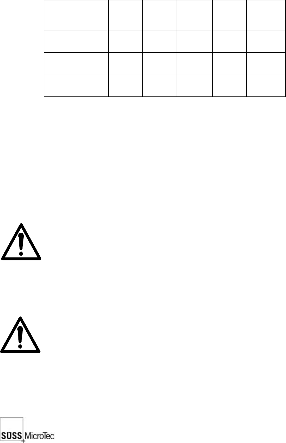
6.1.1 Equipment Data
Physical
Properties
Installed Clearance (mm)
Height (mm) 814 Front 1220
Depth (mm) 950 Back 1220
Width (mm) 950 Left 1220
Weight (kg) 600 Right 1220
Number of pieces min. 2 Top 2500
Environmental Requirements Operate Standby
Ambient Temperature (°C) 5 - 40 N/A
Ambient Humidity (%r.H.) 40 - 60 N/A
Pollution Degree
Grade 1 as per 1 IEC 664 N/A
Clean Room Class Class 6 as per DIN EN ISO 14664-1 N/A
26
SUSS / PA300 / User Manual / M10-121841-00 / February 2002
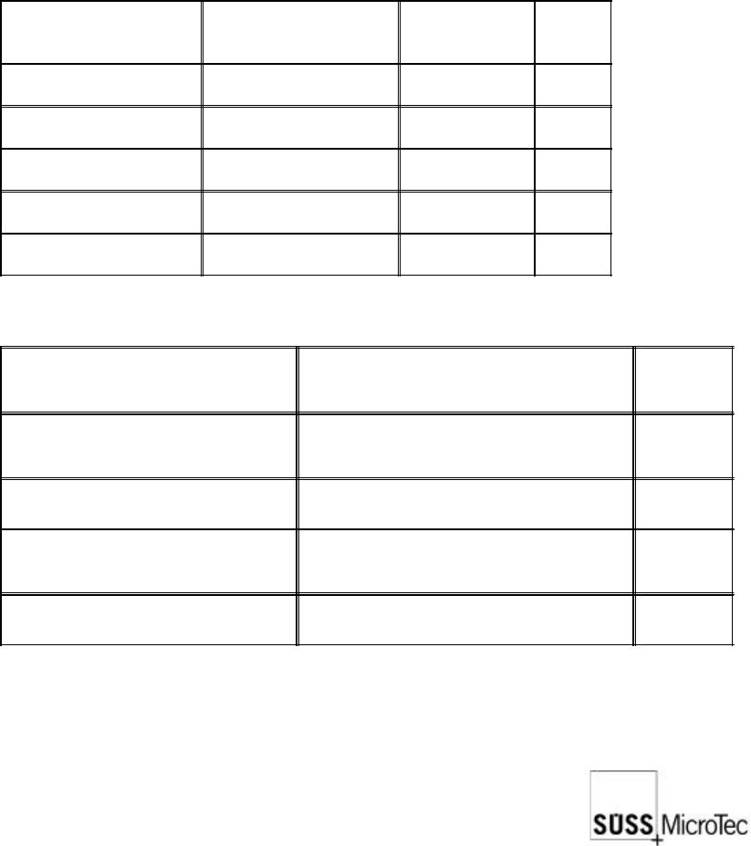
6.1.2 Packaging
The complete PA300 will be delivered in 3 boxes:
Length
(mm)
Width
(mm)
Height
(mm)
Net
Weight
(kg)
Gross
Weight
(kg)
System box
1230 1200 1120 498 607
Table with palette 1050 1000 850 97 102
Accessories 800 1200 800 - approx. 80
The weight of the accessories box is dependent on what has been ordered and will
change accordingly.
It should be noted that all packaging materials are recyclable so it is possible to re-use
them or return them to the supplier.
6.2 Unpacking
The probe system is typically shipped in a crate containing the prober mechanics and
one or more cartons containing the electronics, computer, monitor and accessories.
The prober mechanic is secured on the pallet at four points with the aid of a transportation
frame. After removing the brackets mount the transport rings and ropes, and use a
stabile fork lift (600 kg load min.) to move the mechanics.
Note: To avoid damaging the prober, use the transport frame provided to
move the prober; do not lift the system by the platen or the micro
scope bridge.
Unpack the remaining components.
Delicate components, such as microscope objectives and probeheads, should remain
in individual boxes until ready to install on the prober.
Note: After installing the prober, save all transport locks, handles, screws,
etc. for use in the event that the system must be moved. The return of
a not secured system invalidates all claims on the guarantee.
Before beginning the installation, place the system in its final location unless the limited
accessibility of a light-tight enclosure or clean room prevents assembly there.
SUSS / PA300 / User Manual / M10-121841-00 / February 2002
27
6.3 Mechanical Transport Locks
All movable components of the prober mechanics are secured by transport locks.
These locks must be removed prior to operating the prober.
Note: If the transport locks are not removed prior to operation, this could
result in severe damage.
6.3.1 Platen
The platen is locked in place by four DIN 912 cap screws located at the four corners of
the platen. There are two screws at each corner. One is centered above the column
and secures the platen to the prober; do not remove this screw. The second is offset
from the center of the column and is the transport lock which needs to be removed.
6.3.2 Microscope Movement
The microscope movement transport lock is a bracket located on the right side of
motorized movements. Remove this bracket. A manual movement has 2 brackets, 1
on the front right hand side and 1 on the left front side. They are all clearly marked with
a yellow label.
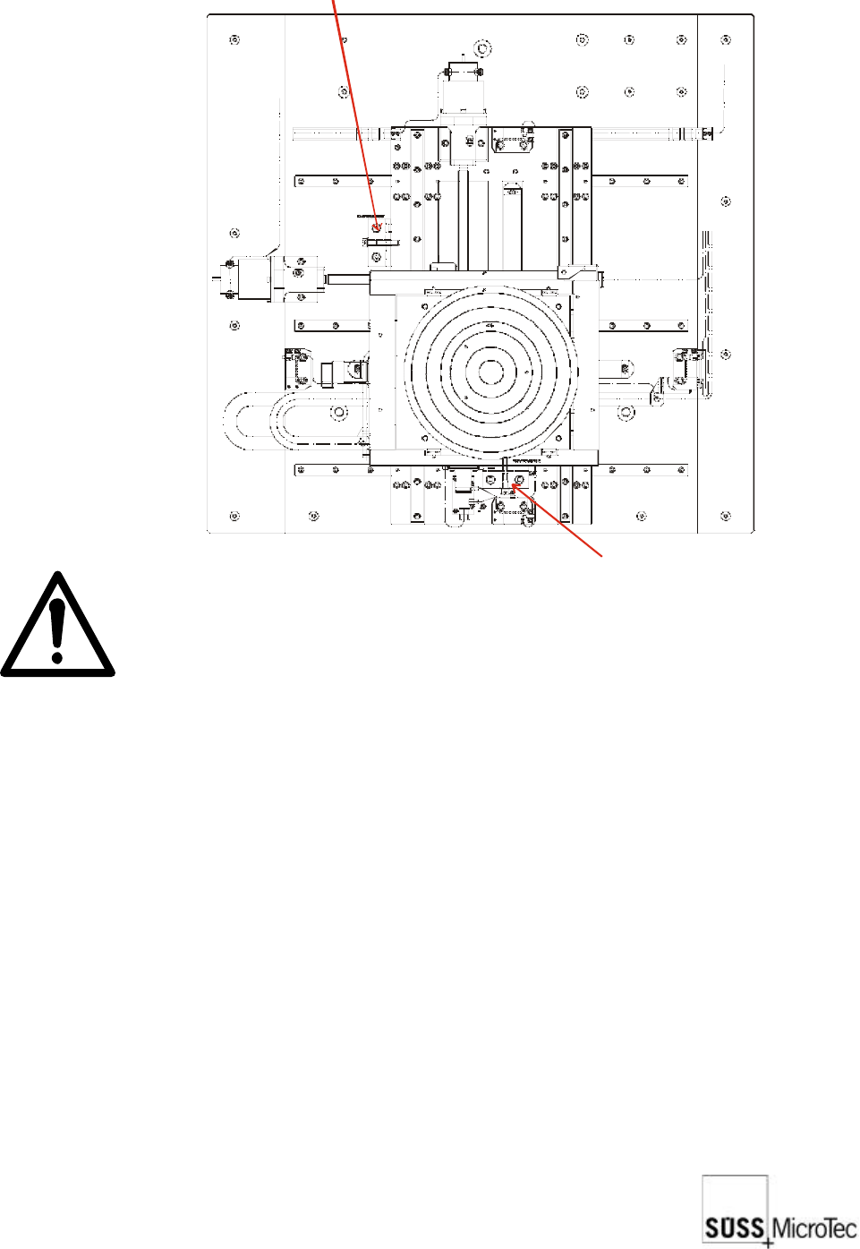
6.3.3 Chuck Stage
The chuck stage is locked by two brackets as illustrated. Remove these brackets. The
stage should now be free to move.
Transport lock for X direction
Transport lock for Y direction