SussPA300UserGuide - 第32页
SUSS / PA300 / User Manual / M10-121841-00 / February 2002 31 7.2.1 System Power-Up System power-up prepares the prober for use from the Joystick Controller and the User Interface. 1. Rotate the Electronics Rack Main Pow…

30
SUSS / PA300 / User Manual / M10-121841-00 / February 2002
7 Operation
7.1 Overview
A one day training in the operation of the system is generally included in the installation
by SUSS personnel or a trained representative. This does not remove the need to
study the operating instructions closely.
The SUSS PA300 Semiautomatic Probe System is a high-performance analytical prober.
The minimum configuration is a fully motorized chuck stage, including x, y, z and theta.
Standard options include motorized microscope x, y, focus and turret, and motorized
probeheads. It is equipped with the ProberBench
®
Operating System for maximum
ease-of-use, flexibility and connectivity.
The system’s electronic rack houses all motor drivers, I/O circuits and power supplies.
An Emergency Machine Off (EMO) circuit, with buttons on the mechanic and electronic
rack, is designed to meet S2-93 standards. A powerful command set, standard RS232,
and optional IEEE488 interfaces, provide flexibility for connecting to testers and control
computers.
The prober’s user interface consists of a joystick controller and a Windows
®
interface
on a PC. The joystick control provides hands-off control of all prober movements, as
well as setting index, setting and going home and contact, 2-point alignment and start
flag. It is ideal for simple, hands-off probing or for the basic wafer set-up required
when interfaced to a tester.
The ProberBench
®
User Interface provides complete control of SUSS probers. This
includes an on-screen joystick, parameter entry such as wafer diameter, stepping index
and contact position, prompted routines, for example, theta alignment and the recording
of step-and-repeat patterns. All parameters, user preferences and options, as well as
which windows are open and their positions are saved in project files so you can
immediately return to your task without setting up. Although not required to operate the
probe system, the user interface offers programmed automation, data acquisition and
much greater control than using the joystick controller alone.
7.2 Electronics Rack
The Electronics Rack consists of the drive and control circuitry for powering a fully
equipped probe system. This includes the chuck stage x, y, z and theta, microscope x,
y, focus and turret and four probeheads with x, y and z. Also accommodated are an
IEEE488 card, two contact sense cards and a peripheral interface for controlling the
microscope illuminator, laser trigger, test beacon and an auxiliary port. A RS232 port is
used to communicate with the PC. The only user controls are the EMO Main Power
Switch and Off and On Buttons.
SUSS / PA300 / User Manual / M10-121841-00 / February 2002
31
7.2.1 System Power-Up
System power-up prepares the prober for use from the Joystick Controller and the
User Interface.
1. Rotate the Electronics Rack Main Power Switch to the On position. The green
lamp will light indicating power to the electronics and the EMO System. Press the
green On button. The integral green lamp will light. If the lamp is not lit, ensure the
latching EMO button on the mechanic is in the released position.
Note: The boot up sequence of the User Interface, running on the PC,
includes establishing communications with the Electronics Rack.
Therefore the electronics must be on before starting the User Interface
to prevent a communications error.
If an error occurs, turn on the electronics and click OK in the error message box.
2. Turn on power to the PC, monitor and all ancillary equipment, such as the
microscope illuminator, laser cutter and camera.
3. The system is now ready for use with the Joystick Controller or from Microsoft
Windows
®
.
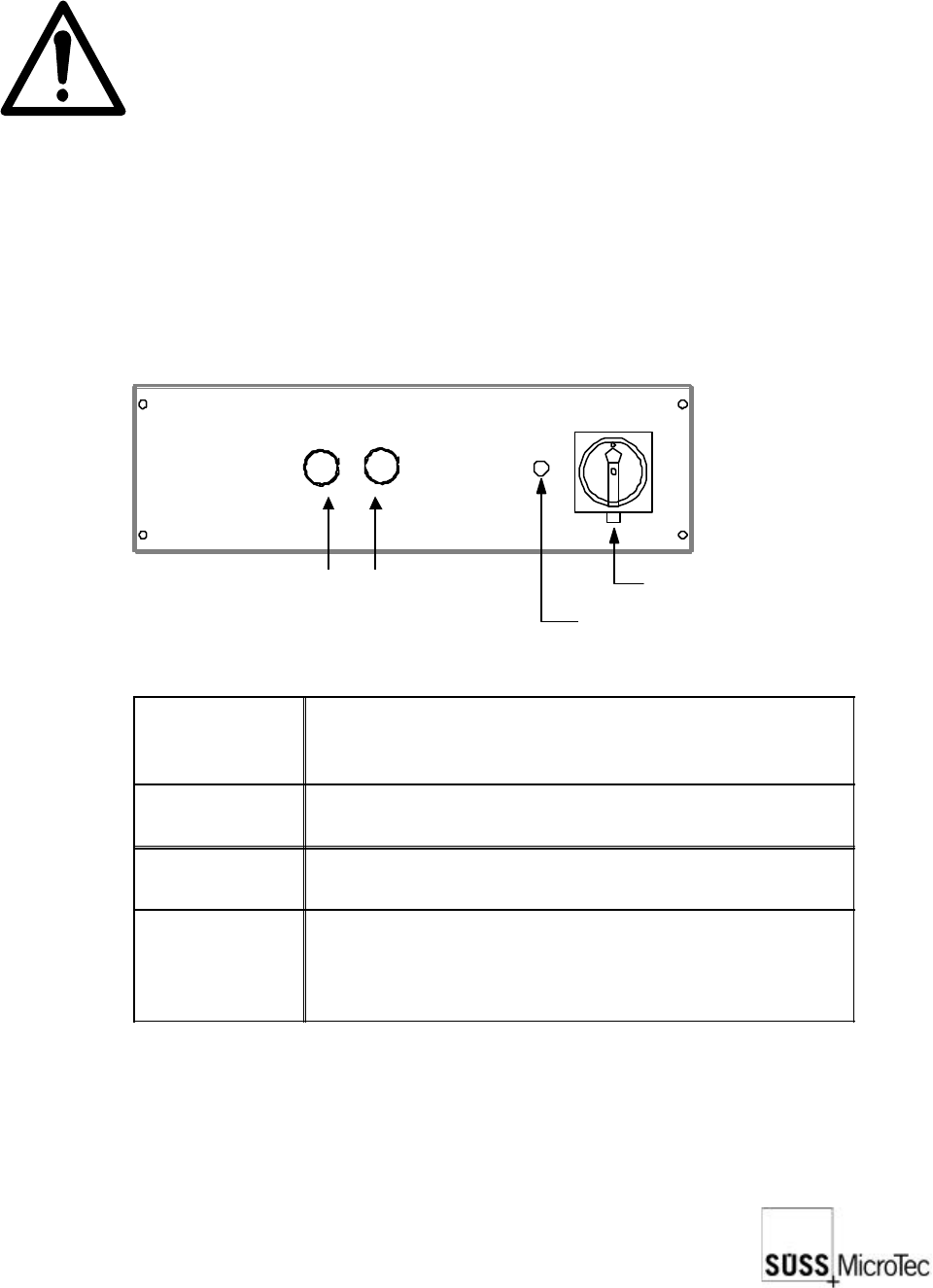
7.2.2 Controls and Functions
Main Power Switch (EMO)
Power On Lamp
On Button (green)
Off Button (red)
EMO Main
Power Switch
Applies power to the electronics rack and to the EMO
system. Power is supplied to the entire system by
pressing the On button.
Power On
Lamp
Illuminated when the Main Power Switch is on and the
specified line voltage is present.
Off Button
Stops all machine movement and removes all
voltages except the 24 VAC EMO power supply.
On Button
Used to energize the EMO system to apply power to
the probe system. The integral green lamp is lit when
the system is ready for use. The EMO Main Power
Switch must be on for the On button to be operable.
32
SUSS / PA300 / User Manual / M10-121841-00 / February 2002
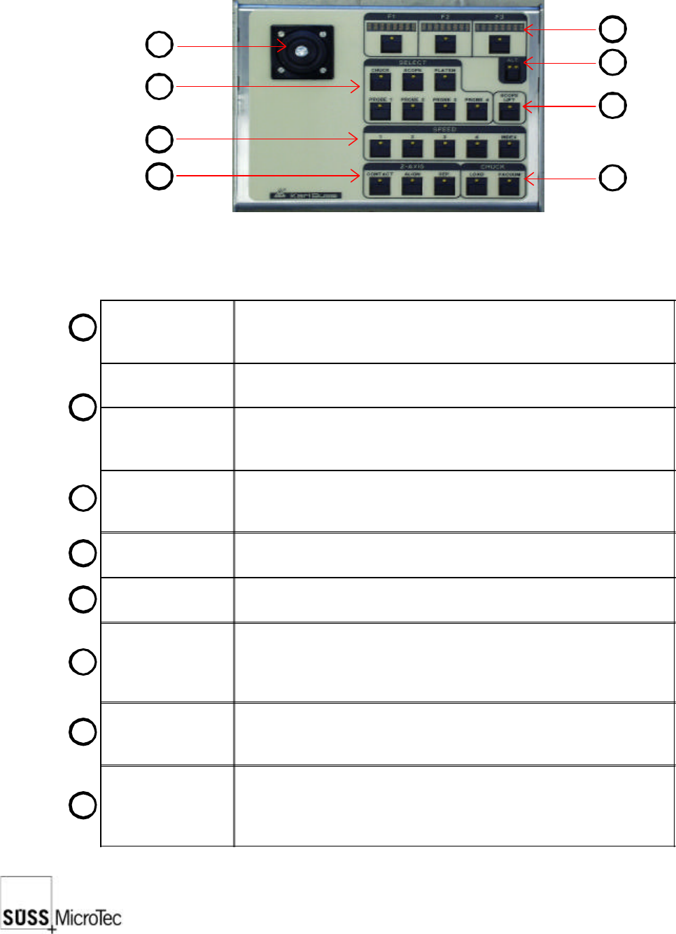
7.3 Joystick Controller
The Joystick Controller provides remote control of all probe system motorized stages
including wafer chuck, microscope, probeheads and platen. The most common
functions, such as load, vacuum, go and set home and contact and two-point alignment
are also provided. It can be used with or without a PC.
Joystick
Used to move motorized stages in the X and Y axes. The joystick
provides proportional control based on the amount of joystick
deflection.
LED Displays (3x)
Indicates the use of the F1-F3 function key below it and updates
each time the Alt key is pressed.
F1-F3 Function
Keys
Used in conjunction with the Alt Key to provide 12 additional
functions. Pressing the key will either carry out the function or
redefine the keys with new functions.
Alt Key
A four-state key as indicated by its LEDs: off-off, off-on, on-off and
on-on. Each press of the Alt key will display the next three functions
in the LED displays.
Lift Key
Raises the microscope to change objectives or facilitate setup. The
LED is lit when the microscope is up.
Select Keys (7x)
Defines the stage to be controlled by the joystick and which stage
the function keys relate to.
Speed Keys (5x)
Sets the speed at which stages move in response to the joystick.
Speed 1: jogs or moves at the smallest stepping increment
Speed 2-4: each cover a speed range (4 = 100%)
Index: moves at a user-defined index value in X or Y direction.
Z-Axis Keys (3x)
Moves the selected stage or probehead to the defined contact, align
and separate positions. Contact must be set by the user before
these keys are operational.
Chuck Keys (2x)
Load lowers the chuck to the lowest or load position, centers in the
X axis and forward towards the user.
Vacuum controls the vacuum to the chuck stage for securing the
wafer or DUT.
1
1
2
3
4
5
6
7
8
2
3
4
8
7
6
5