SussPA300UserGuide - 第36页
SUSS / PA300 / User Manual / M10-121841-00 / February 2002 35 REAL POS switches the display to the stage position in µm from the home position. F1 displays the X distance, F2 the Y value and F3, the Z position QUIET swit…

34
SUSS / PA300 / User Manual / M10-121841-00 / February 2002
7.3.2 F1-F3 Function Keys
Key LEDs F1 F2 F3
Off-off
Off-on
On-off
On-on
ALIGN
SET CONT / SET FOC
REMOTE
IDX POS
GO HOME
Z UP
THETA
REAL POS
SET HOME Z
DOWN
INDEX
QUIET / TURRET
ALIGN redefines the keys as CANCEL, MARK 1 and MARK 2, and starts the 2-point
alignment process.
1. To begin, position the wafer stage near the left (right) edge of the wafer so a
horizontal street or feature is aligned with a crosshair or probe tip reference point
and press MARK 1.
2. Move to the right (left) edge of the wafer and align with the same street or feature
and press MARK 2. The chuck theta will then rotate to correct the rotational error.
Increased magnification and careful alignment increases accuracy.
The same procedure can be used for theta alignment of the microscope and
probeheads. Although the chuck is physically rotated, the microscope and probeheads
are corrected with software. This allows the probehead rotational correction to track
the microscope, so aligning a microscope will automatically align the probeheads.
Packaged parts are easier to align to with the microscope rather than with the chuck.
GO HOME moves the selected stage to the X-Y home position as defined with Set
Home.
SET HOME defines the X-Y home position at the current position and zeros the X-Y
co-ordinates.
SET CONT defines the upper limit of chuck travel, set to provide adequate contact
without device or probe tip damaging excessive overtravel. When set, the function
becomes CL CONT to clear the contact position. The contact position must be set
each time the system is powered-up. The Z-Axis controls of Contact, Align and Separate
cannot be used until contact has been set. When choosing the microscope movement,
SET FOC is displayed – this saves the focus height. With CONTACT it is then moved
into its stored position.
Z UP moves the chosen stage upward at the selected speed.
Z DOWN moves the chosen stage downward at the selected speed.
REMOTE sets a flag to signal a tester the prober is ready, redefines the key as LOCAL
and disables all controls except this button. Pressing LOCAL resets the ready flag and
enables local controls.
THETA redefines the keys as CW, CENTER and CCW and controls the chuck theta in
clockwise, go to center and anticlockwise.
INDEX redefines the keys as X AXIS, Y AXIS and CANCEL. X and CANCEL Y indicate
the index value and may be changed using the joystick. After setting the index, press
the F1 and F2 keys to record. CANCEL exits the procedure.
IDX POS switches the display to show the current position in relation to the home
position in multiples of the set. F1 displays the X distance and F2, the Y value.

SUSS / PA300 / User Manual / M10-121841-00 / February 2002
35
REAL POS switches the display to the stage position in µm from the home position. F1
displays the X distance, F2 the Y value and F3, the Z position
QUIET switches on the quiet mode. Once the control position has been reached,
electricity is taken away from all motors to reduce electrical noise interference to the
device under test.
TURRET Changes microscope objective. Display changes to DEC INC and chooses
the next smaller / larger objective.
7.4 PA300 Mechanic Assembly
The PA300 Semiautomatic Prober has a fully motorized chuck stage consisting of x, y,
z and theta, and typically a motorized microscope movement of x and y axes. Additionally
the platen, microscope focus and nosepiece and up to four motorized probeheads
may be installed. A pin drive is integrated in the Z axis.
7.4.1 Microscope Movement
The microscope movement mounts the microscope to the prober and provides a means
of viewing beyond the field of view when the chuck cannot be moved because probes
are in contact. The microscope movement consists of x and y axis translation and a
microscope lift; the microscope typically has a manual focus or z axis and nosepiece
controls, which can also be motorized.
There are several microscope movements available:
• Motorized,
• Manual coaxial knob type,
• Adjustable.
Motorized
All microscope x and y axes control, as well as a motorized focus and nosepiece, is
performed from the PC-based User Interface or Joystick Controller.
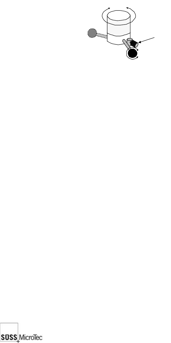
Manual Coaxial
To change the position of the microscope use the knobs located on the right side of the
microscope movement. The Drag Lever sets the amount of resistance for precise feel.
Adjustable
The Adjustable Mount is a fixed microscope mount with an adjustable fixed position.
This allows the microscope to be coarsely positioned or centered over the probe tips.
7.4.2 Platen and Controls
The platen supports the probeheads and probecard. The typical configuration is for
vacuum base probeheads and a manual movement mount. Other configurations can
include magnetic, bolt-down and clamping probehead bases, as well as fixed mount.
The lid should only be opened for loading and unloading of wafers and substrates but
should be closed during operation.
36
SUSS / PA300 / User Manual / M10-121841-00 / February 2002
Manual Movement
The manual platen movement control knob is located at the left front corner of the
prober and provides a precise contact/separation stroke and a coarse set-up range.
contact
position
separate
position
raise lower
secured
adjust
lock
Separation/Contact Lever: the lever of the platen control knob provides 0.4
mm of travel to facilitate precise simultaneous
separation or contact of probe tips. A clockwise
rotation raises the platen for separation.
Platen Height Adjustment Knob: the large knurled knob provides up to 35 mm of
platen height adjustment to accommodate test
fixtures of various heights. This knob is locked in
place by the separation/contact lever. To adjust,
turn the lever a quarter of a turn anticlockwise;
the adjustment knob is now free to turn. A
clockwise movement raises the platen. Secure
by turning the lever clockwise.
Platen Lock: the small knurled knob locks the platen in the
current position. To lock, turn the lock knob inward.
Platen Travel Indicator: the dial indicator located on the rear left side of
the platen provides a means to determine the
amount of platen travel. A clockwise movement
indicates that the platen is rising.
Probehead Mounting Options
Vacuum: Vacuum relies on the system vacuum, also used to secure the
wafer to the chuck, to secure the probeheads. Vacuum is
distributed using six-port manifolds located on both sides of the
prober on the microscope bridge. Shutoffs for each probehead
are provided and when not in use should be closed to preserve
maximum system vacuum.
Bolt-down: Bolt-down is used in high frequency applications due to the
stability required for semi-rigid cables. Also probe-heavy
probeheads could unbalance, damaging the tips, if vacuum is
lost with vacuum secured probeheads.