SussPA300UserGuide - 第38页
SUSS / PA300 / User Manual / M10-121841-00 / February 2002 37 Platen Cable Clamps Cable clamps are provided to secure electrical connections and/or vacuum hoses. Chuck Stage All stage movements are DC servo motor driven …
36
SUSS / PA300 / User Manual / M10-121841-00 / February 2002
Manual Movement
The manual platen movement control knob is located at the left front corner of the
prober and provides a precise contact/separation stroke and a coarse set-up range.
contact
position
separate
position
raise lower
secured
adjust
lock
Separation/Contact Lever: the lever of the platen control knob provides 0.4
mm of travel to facilitate precise simultaneous
separation or contact of probe tips. A clockwise
rotation raises the platen for separation.
Platen Height Adjustment Knob: the large knurled knob provides up to 35 mm of
platen height adjustment to accommodate test
fixtures of various heights. This knob is locked in
place by the separation/contact lever. To adjust,
turn the lever a quarter of a turn anticlockwise;
the adjustment knob is now free to turn. A
clockwise movement raises the platen. Secure
by turning the lever clockwise.
Platen Lock: the small knurled knob locks the platen in the
current position. To lock, turn the lock knob inward.
Platen Travel Indicator: the dial indicator located on the rear left side of
the platen provides a means to determine the
amount of platen travel. A clockwise movement
indicates that the platen is rising.
Probehead Mounting Options
Vacuum: Vacuum relies on the system vacuum, also used to secure the
wafer to the chuck, to secure the probeheads. Vacuum is
distributed using six-port manifolds located on both sides of the
prober on the microscope bridge. Shutoffs for each probehead
are provided and when not in use should be closed to preserve
maximum system vacuum.
Bolt-down: Bolt-down is used in high frequency applications due to the
stability required for semi-rigid cables. Also probe-heavy
probeheads could unbalance, damaging the tips, if vacuum is
lost with vacuum secured probeheads.

SUSS / PA300 / User Manual / M10-121841-00 / February 2002
37
Platen Cable Clamps
Cable clamps are provided to secure electrical connections and/or vacuum hoses.
Chuck Stage
All stage movements are DC servo motor driven with encoder positioning feedback.
Stage control is from the ProberBench User Interface or Joystick Controller. No manual
controls are required.
Vacuum Hold-down Adjustment
The vacuum chuck has provisions to adjust the vacuum hold-down for various size
wafers. To change the wafer size, unscrew and remove the current seal-pin. Insert
and screw in the appropriate length seal-pin. The unused seal-pins are usually stored
on the front left hand side of the system.
Chuck Grounding and Biasing
The chuck is isolated from ground and a lead is provided from the chuck to a banana
jack at the right rear corner of the prober mechanic. At this point the jack can be
connected to ground with the ground jack provided, or connected to a bias voltage
source.
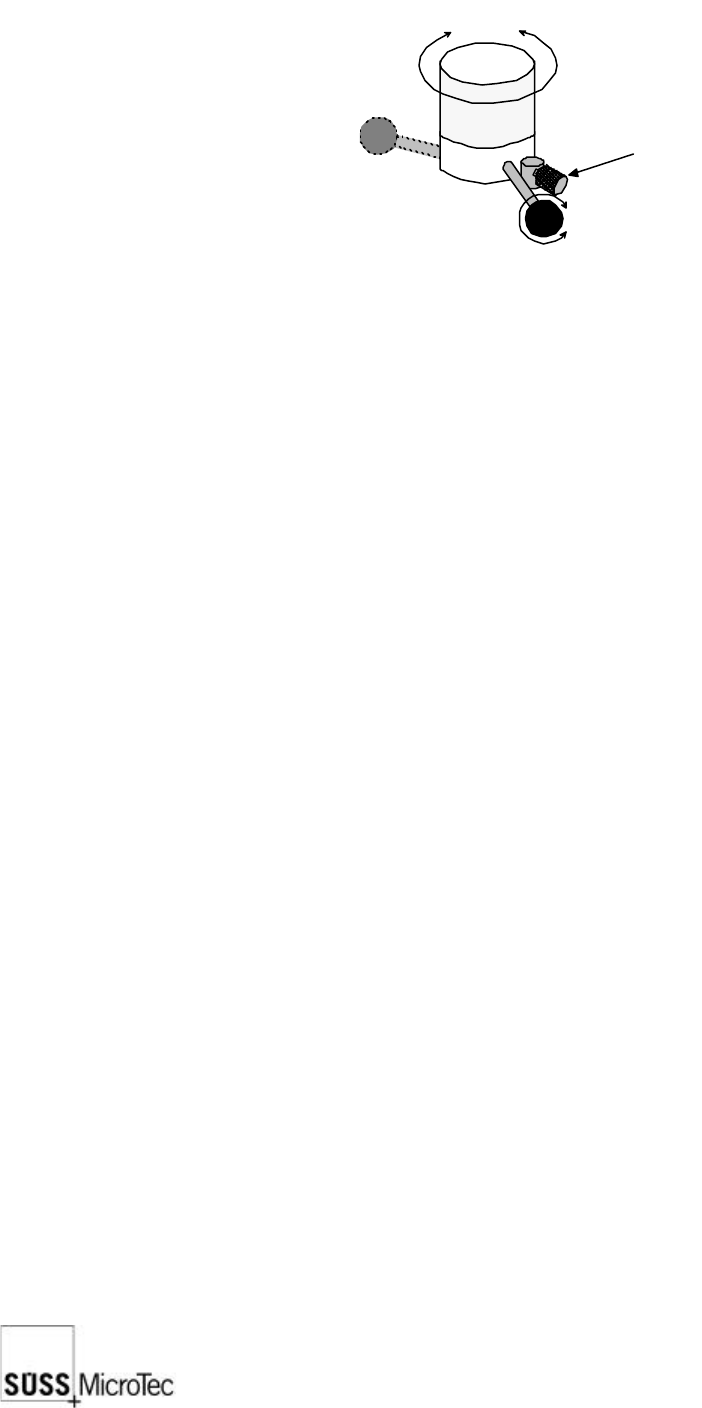
Pin Drive
The pin drive is integrated into the Z-Axis and because the pins are fixed, one controls
them with the movement of the Z-Axis, an automatic interlock prevents damage
occurring to the wafer. If the wafer is lying on the chuck and held by vacuum, the
movement of the Z-Axis is restricted so that the pins stay in the chuck. After switching
off the vacuum, the chuck can be driven as far as the wafer unloading height and the
pins stand finally about 5-6mm away.
38
SUSS / PA300 / User Manual / M10-121841-00 / February 2002
8 User Maintenance
8.1 General Maintenance
The short time spent performing a short visual inspection will greatly improve the overall
performance of the system. Furthermore, be alert at all times to any unusual system
noises, behavior or changes in operating performance or the results which may be
symptomatic of problems which could damage the system if left uncorrected.
8.2 Visual Checks
It is very important to conduct a thorough visual check of the system on a daily basis.
Key areas include the chuck surface, movements of the wafer stage x, y, z and theta,
microscope stage X and Y, platen and the individual probeheads. All movements should
exhibit smooth transit without any irregularities. Also inspect for scratches and other
signs of wear and tear. A poorly maintained instrument will not meet designed
performance specifications.
8.3 Safety Interlock Switch
The safety interlock switch can be found underneath the probe head platen, on the left
side of the long rotational axis of the covering lid. The operator is obliged to carry out
tests on this switch at least every 6 months.
8.4 Mechanical Adjustments
These maintenance procedures will help to ensure system accuracy and reliability.
8.4.1 Chuck Planarizing Procedure
If upgrading with a thermochuck through SUSS, planarization will be undertaken by
qualified SUSS personnel or representative
Chuck planarizing or levelling ensures equal probe contact force from tip-to-tip of
probecards and throughput the range of travel of the chuck. It has been planarized at
the factory and checked, and adjusted if required, at installation. It generally will not
become unplanarized with use, but if you notice that at high magnifications the chuck
goes out of focus in areas of the chuck, planarization is required. If the chuck has been
removed or changed planarization should be checked.
Procedure
1. Remove both halves of the black cover on top of the chuck stage. Use the joystick
to move the chuck for access to the screws and clearance to remove the covers.
Do not remove the safety covers!