SussPA300UserGuide - 第58页
SUSS / PA300 / User Manual / M10-121841-00 / February 2002 57 11 Health Hazard Analysis 11.1 Process Health Hazard Analysis 11.1.1 Use of Instruments The semi-automatic prober PA300 is designed as a lab instrument accord…
56
SUSS / PA300 / User Manual / M10-121841-00 / February 2002
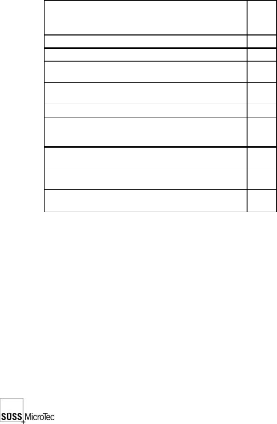
10.4 Installation Checklist
This is the Installation Checklist for the SUSS PA300 Semiautomatic Prober. Review
and complete the check points to ensure proper installation and operation.
All transport locks have been removed, including microscope
movement, platen and chuck stage
All components and accessories have been installed
All electrical interconnects are made and secured
Non-electrical utilities are connected, including vacuum and air
All components requiring AC power are plugged into outlets with
the required voltage and VA or wattage
Apply power and ensure the EMO system operates (including the
loading lid interlock)
Check functionality of all components
Check operation of chuck stage, microscope movement and
platen, ensuring free and smooth movement throughout their
entire range of travel
Check (and adjust if required) the planarity of the chuck stage
and microscope movement
Ensure all safety covers, panels and enclosures are installed or
secured
Ensure that the customer is trained in the proper operation of the
system

SUSS / PA300 / User Manual / M10-121841-00 / February 2002
57
11 Health Hazard Analysis
11.1 Process Health Hazard Analysis
11.1.1 Use of Instruments
The semi-automatic prober PA300 is designed as a lab instrument according to DIN
EN 61 010 T1: 1994-03.
It is intended for use on industrial processes and laboratory applications.
As an electro-mechanical tool together with measurement instruments, it is used for
testing and probing wafers.
It’s specific task is the postitioning of probe needles in contact with semiconductor
structures.
It is assumed that the operator and service personnel are properly trained and that
they are periodically retrained for unexpected hazards.
As a lab instrument the PA300 prober should provide for universal set up and
applications.
11.1.2 Safety Conception
Mechanics
1. Normal Operation
After opening the loading lid during normal operation, the x-y stage will come to
a standstill in order to avoid the risk of injury to the operator. The control panel
should be kept separate to the PA300 operating area. There should be no
other potential risks during this type of operation.
During the application operation, handling creates no further hazards. Openings
to moving parts can only be reached via the loading lid with interlock.
Moving parts are potentially hazardous to the operator but can only be touched
when not in application operation. It should be noted that materials outside the
device can also be effected e.g. when unloading and positioning the wafer.
Unintentional touching has been reduced to a minimum but conscious access
to the chuck and the probecard area have been left.
2. Alignment Area
Parts which move quickly and with force towards a mechanical stop are protected
by screw on covers (e.g. x-y stage). The motorized microscope and probe
head motions are slow. They sit outside the operating area and do not run to a
stop. Openings caused by unused parts (e.g. the probecard) stay open as
during normal operation access is not needed.
3. Further Risks
Further risks for untrained personnel are relatively low.
The emergency OFF function is set according to Stop-Category 0: a complete
standstill is carried out through the immediate shutting off of the energy sources.
The emergency OFF function should always be used in the case of an
emergency. It can also be set to protect the measuring device against
programming errors. Control errors may affect the mechanics but the OFF
function prevents damage to the system and to the test objects by effecting an
immediate standstill.

58
SUSS / PA300 / User Manual / M10-121841-00 / February 2002
By following the guidelines set out in this manual injuries to personnel can be
minimized and damage to the system and materials prevented.
4. Guidelines in User Information
Safety instructions can be found in the appropriate chapters of this manual.
Following these will help to minimize danger.
11.2 Electronics
11.2.1 Basic Design
The electrical equipment contains a separate control panel which is connected with a
line cord to 230V 1 phase AC. This control panel is protection class 1. The PA300
prober is supplied with a safety low voltage of <30V.It is connected via a earth wire to
the control panel. The EMO supply voltage is separate and fulfils the requirements of
a safety low voltage smaller than 30V AC. There are no special risks.
11.2.2 Guidelines for Electronics in the User Information
The accident prevention guidelines for electrical and operational facilities should be
taken into consideration. The user has to ensure that the electrical and operational
facilities are periodically tested.
11.3 Radiation
Standard configuration produces no special risks in terms of radiation.
For possible HF interference from outside guidelines are given, but the operation should
not be influenced.
11.4 Earthquake Safety
Earthquake protection for the PA300 consists of interlocking coupling between the
table and the prober.
11.5 Total Risk Evaluation
The chances of injury have been reduced as they are dependent on several events
occurring at the same time:
• Irresponsible behaviour of the operator
• Accidental motion in the danger area