182050 User manual.pdf - 第126页
semi automatic ',$*126 7,&6 6<67(0 4.4 User Manual Software Version 0 7SP02 NM1 Group 3 NM1 Group 4 MMOV1 Group 0 (X13) MMOV1 Group 1 (X13) NM 1 Group 3 Point Description --------------------- --------- -----…
semi automatic
',$*1267,&6
6<67(0
Software Version 07SP02 User Manual 4.3
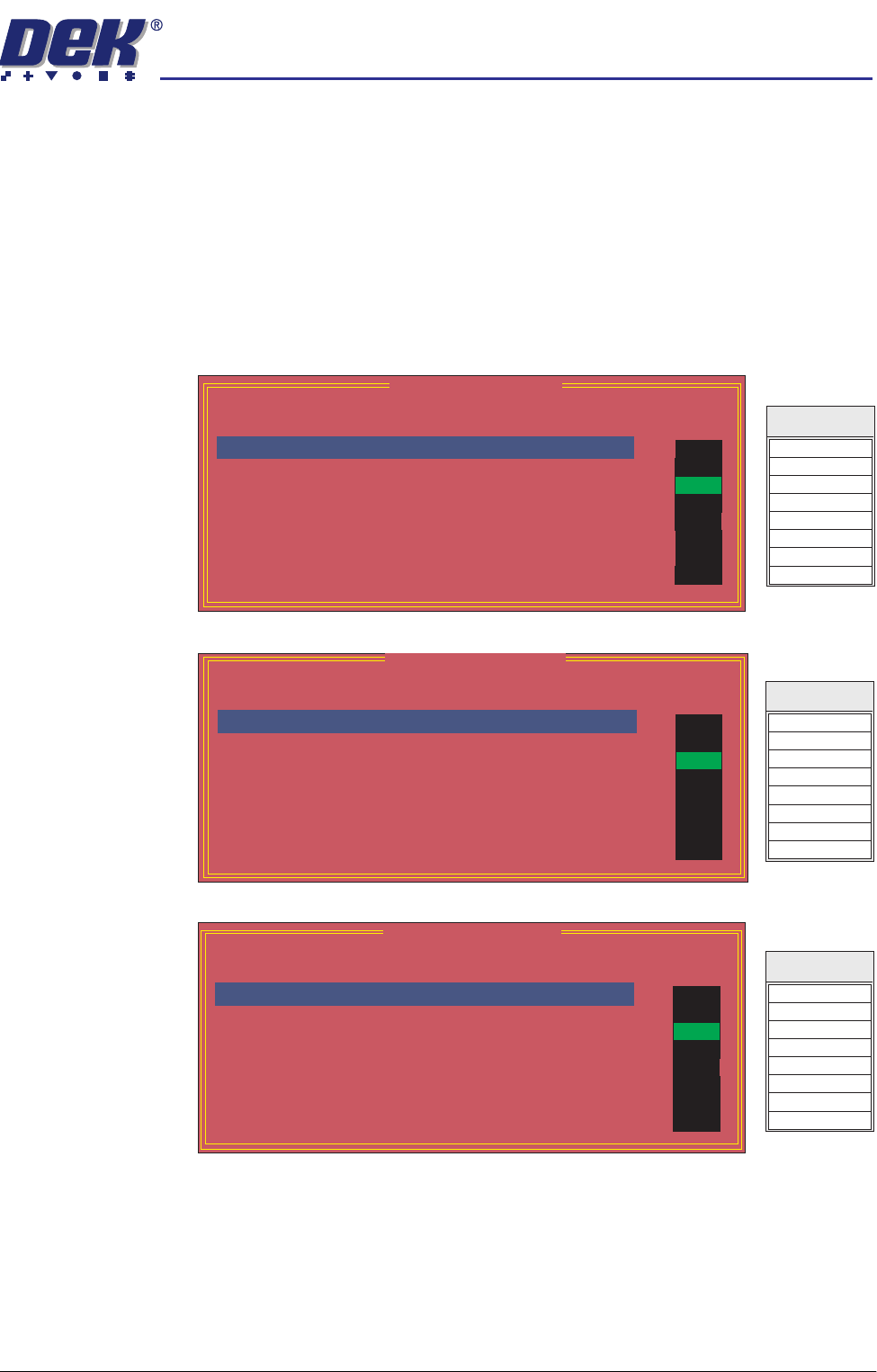
NM1 is a NextMove I/O card that is housed in the PC. The MMOV1 and MMOV
2 are MultiMove I/O cards that are housed in the machine controller enclosure.
NextMove cards have up to five groups, G0 - G4 and MultiMove cards four
groups, G0 - G3. The NextMove and MultiMove cards monitor and control
various drives and control cards in the machine controller enclosure.
NOTE
The signal listings, shown on the right hand side of the following diagnostic
windows, are not shown on the MMI screen, they are included here as an aid
to show the relationship between the I/O signal and the point description.
NM1 Group 0
NM1 Group 1
NM1 Group 2
NM 1 Group 0
Point Description
---------------------
---------
-------
Bit No
Sense
-----------
------
Direction
State
Table HOME
Table LIMIT
Table at Home
Rail Lifted Left
Rail Lifted Right
Camera X HOME
Print Carriage HOME
Servo Amp error
0
1
2
3
4
5
6
7
Positive
Positive
Negative
Negative
Negative
Positive
Positive
Positive
Input
Input
Input
Input
Input
Input
Input
Input
OFF
ON
OFF
OFF
OFF
OFF
OFF
OFF
DIG IN 0
DIG IN 4
DIG IN 1
Signal
DIG IN 5
DIG IN 6
DIG IN 2
DIG IN 3
DIG IN 7
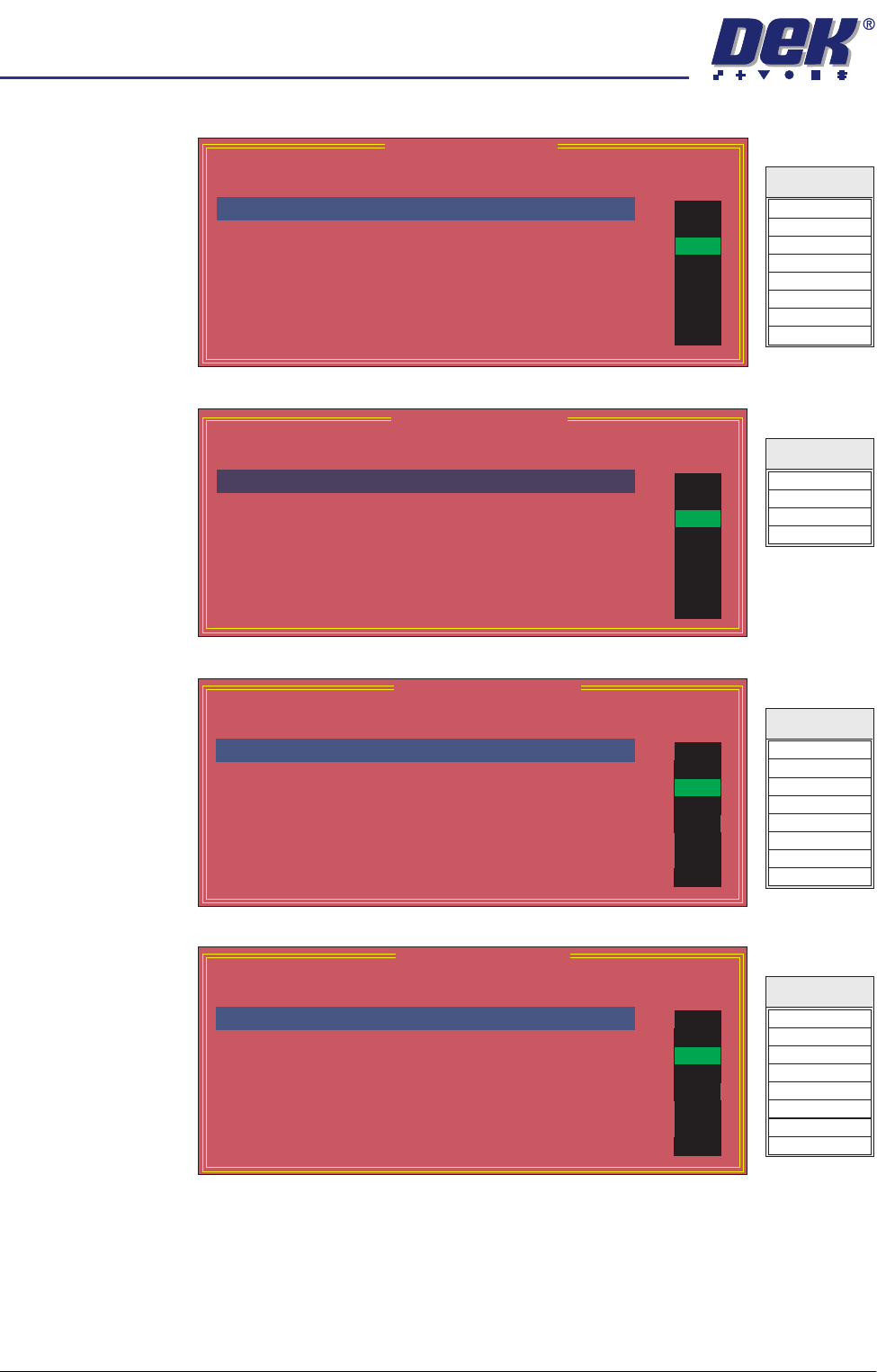
NM 1 Group 1
Point Description
---------------------
---------
-------
-----------
------
Bit No
Sense
Direction
State
X Rear INDEX
X Rear HOME
X Forward INDEX
X Forward HOME
Y Actuator INDEX
Y Actuator HOME
MUX HOME
Camera Y HOME
0
1
2
3
4
5
6
7
Positive
Positive
Positive
Positive
Positive
Positive
Positive
Positive
Input
Input
Input
Input
Input
Input
Input
Input
OFF
ON
OFF
OFF
OFF
OFF
OFF
OFF
DIG IN 8
DIG IN 12
DIG IN 9
Signal
DIG IN 13
DIG IN 14
DIG IN 10
DIG IN 11
DIG IN 15
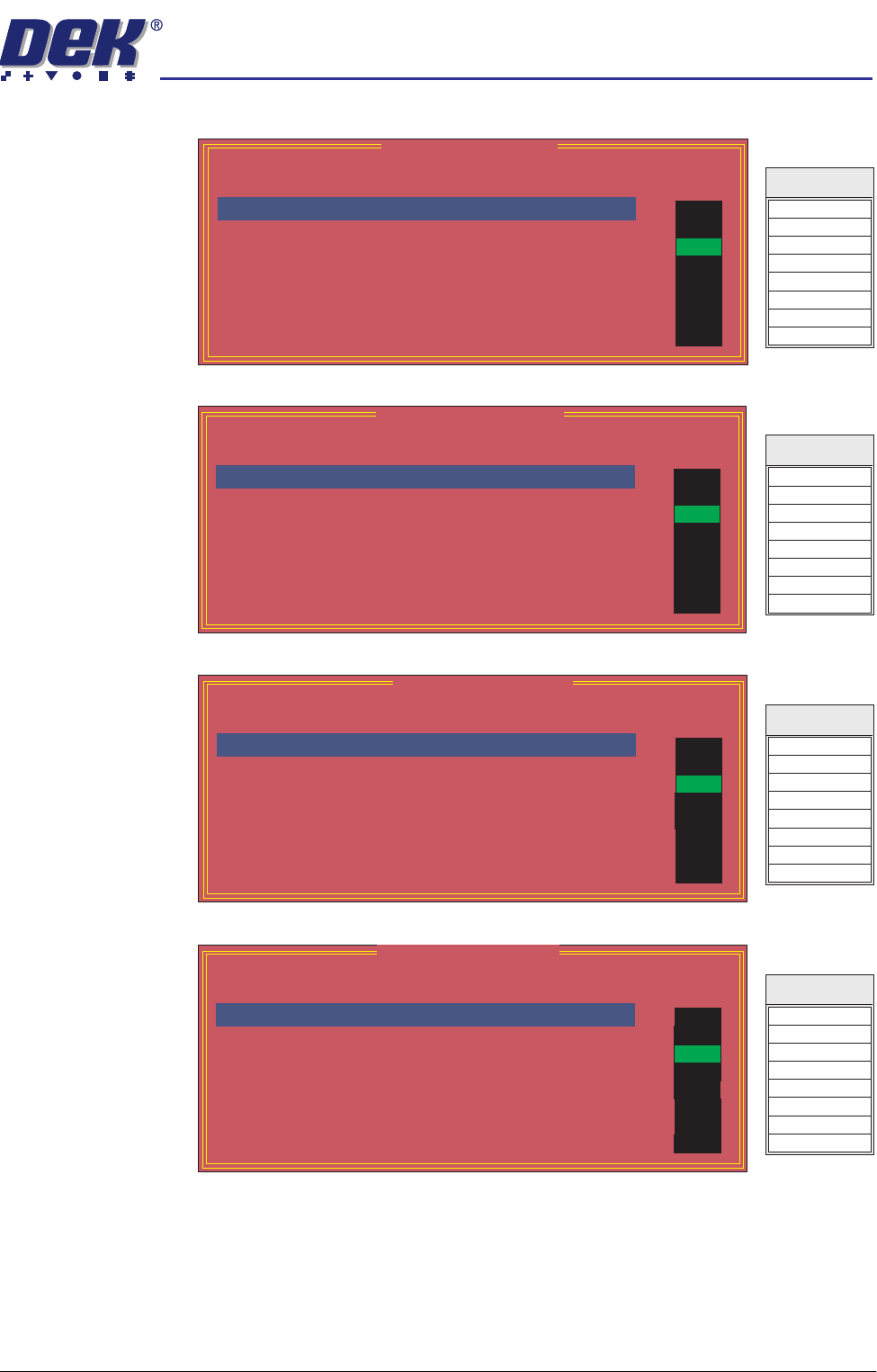
NM 1 Group 2
Point Description
---------------------
---------
-------
-----------
------
Bit No
Sense
Direction
State
Board At Left
Board At Right
Not Used
Not Used
Not Used
Not Used
Board At Stop
Board Stop In
0
1
2
3
4
5
6
7
Negative
Negative
Positive
Positive
Positive
Positive
Negative
Negative
Input
Input
Input
Input
Input
Input
Input
Input
OFF
ON
OFF
OFF
OFF
OFF
OFF
OFF
DIG IN 16
DIG IN 20
DIG IN 17
Signal
DIG IN 21
DIG IN 22
DIG IN 18
DIG IN 19
DIG IN 23
semi automatic
',$*1267,&6
6<67(0
4.4 User Manual Software Version 07SP02
NM1 Group 3
NM1 Group 4
MMOV1 Group 0
(X13)
MMOV1 Group 1
(X13)
NM 1 Group 3
Point Description
---------------------
---------
-------
-----------
------
Bit No
Sense
Direction
State
Not Used
Not Used
MIU Send Upline A
MIU Send Downline A
MIU Available Out A
Not Used
Not Used
Not Used
0
1
2
3
4
5
6
7
Positive
Positive
Positive
Positive
Positive
Positive
Positive
Positive
Output
Output
Output
Output
Output
Output
Output
Output
OFF
ON
OFF
OFF
OFF
OFF
OFF
OFF
DOP 0
DOP 4
DOP 1
Signal
DOP 5
DOP 6
DOP 2
DOP 3
DOP 7
NM 1 Group 4
Point Description
---------------------
---------
-------
-----------
------
Bit No
Sense
Direction
State
MUX control bit 0
MUX control bit 1
MUX control bit 2
Servo Amp enable
Not Used
Not Used
Not Used
Not Used
0
1
2
3
4
5
6
7
Positive
Positive
Positive
Positive
Positive
Positive
Positive
Positive
Output
Output
Output
Output
Output
Output
Output
Output
OFF
ON
OFF
OFF
OFF
OFF
OFF
OFF
Signal
DOP 8
DOP 9
DOP 10
DOP 11
MMOV 1 Group 0
Point Description
---------------------
---------
-------
-----------
------
Bit No
Sense
Direction
State
Right Jog Button
Left Jog Button
Not Used
Power On Monitor
Not Used
Cleaning Unit Home
Paper Low
Solvent Low
0
1
2
3
4
5
6
7
Positive
Positive
Positive
Positive
Negative
Negative
Negative
Negative
Input
Input
Input
Input
Input
Input
Input
Input
OFF
ON
OFF
OFF
OFF
OFF
OFF
OFF
Signal
IN 0
IN 4
IN 1
IN 5
IN 6
IN 2
IN 3
IN 7
MMOV 1 Group 1
Point Description
---------------------
---------
-------
-----------
------
Bit No
Sense
Direction
State
Not Used
Infinity Hardware
Not Used
Not Used
Not Used
Machine Available A
Downline Ready A
Upline Ready A
0
1
2
3
4
5
6
7
Positive
Positive
Positive
Positive
Positive
Positive
Positive
Positive
Input
Input
Input
Input
Input
Input
Input
Input
OFF
ON
OFF
OFF
OFF
OFF
OFF
OFF
Signal
IN 8
IN C
IN 9
IN D
IN E
IN A
IN B
IN F
semi automatic
',$*1267,&6
6<67(0
Software Version 07SP02 User Manual 4.5
MMOV1 Group 2
(X13)
MMOV1 Group 3
(X13)
MMOV2 Group 0
(X12)
MMOV2 Group 1
(X12)
MMOV 1 Group 2
Point Description
---------------------
---------
-------
-----------
------
Bit No
Sense
Direction
State
Not Used
Green Beacon
Amber Beacon
Red Beacon
Not Used
ProFlow Reg Output
Cleaner Home Clamp
Chase Clamp
0
1
2
3
4
5
6
7
Positive
Positive
Positive
Positive
Positive
Positive
Positive
Positive
Output
Output
Output
Output
Output
Output
Output
Output
OFF
ON
OFF
OFF
OFF
OFF
OFF
OFF
Totem 0
Totem 1
Totem 2
Totem 3
Totem 4
Totem 5
Totem 6
Totem 7
Signal
MMOV 1 Group 3
Point Description
---------------------
---------
-------
-----------
------
Bit No
Sense
Direction
State
Screen Clamp
Cleaner Blade
Cleaner Vacuum
Clamp Board
Board Stop
Not Used
Not Used
Not Used
0
1
2
3
4
5
6
7
Positive
Positive
Positive
Positive
Positive
Positive
Positive
Positive
Output
Output
Output
Output
Output
Output
Output
Output
OFF
ON
OFF
OFF
OFF
OFF
OFF
OFF
Source 0
Source 1
Source 2
Source 3
Source 4
Source 5
Source 6
Source 7
Signal
MMOV 2 Group 0
Point Description
---------------------
---------
-------
-----------
------
Bit No
Sense
Direction
State
Air Pressure
Screen Present
Lid Bolt Shut
Cartridge Empty
Cartridge Home
Cartridge Away
ProFlow Cassette Low
ProFlow Fitted
0
1
2
3
4
5
6
7
Positive
Positive
Positive
Positive
Negative
Negative
Positive
Positive
Input
Input
Input
Input
Input
Input
Input
Input
OFF
ON
OFF
OFF
OFF
OFF
OFF
OFF
IN 0
IN 1
IN 2
IN 3
IN 4
IN 5
IN 6
IN 7
Signal
MMOV 2 Group 1
Point Description
---------------------
---------
-------
-----------
------
Bit No
Sense
Direction
State
Not Used
Not Used
ProFlow Reg Fitted
Not Used
Not Used
Not Used
Not Used
Not Used
0
1
2
3
4
5
6
7
Positive
Positive
Positive
Positive
Positive
Positive
Positive
Positive
Input
Input
Input
Input
Input
Input
Input
Input
OFF
ON
OFF
OFF
OFF
OFF
OFF
OFF
IN 8
IN 9
IN A
IN B
IN C
IN D
IN E
IN F
Signal