182050 User manual.pdf - 第177页
semi automatic ',163(& 7,21 02'8/( 29(59,(: Software Version 07SP02 User Manual 7.3 Inspection Cycl es During setup, sites are g iven a priori ty of eit her Every Cycle ( EC) or General (G). The a mount …
semi automatic
',163(&7,21
02'8/(29(59,(:
7.2 User Manual Software Version 07SP02
Board Inspection The various board inspections are shown below.
NOTE
Uneven tinning of the board and/or misaligned solder mask may be seen as
paste, which could cause false readings. DEK’s grey camera and lighting setup
can eliminate this effect.
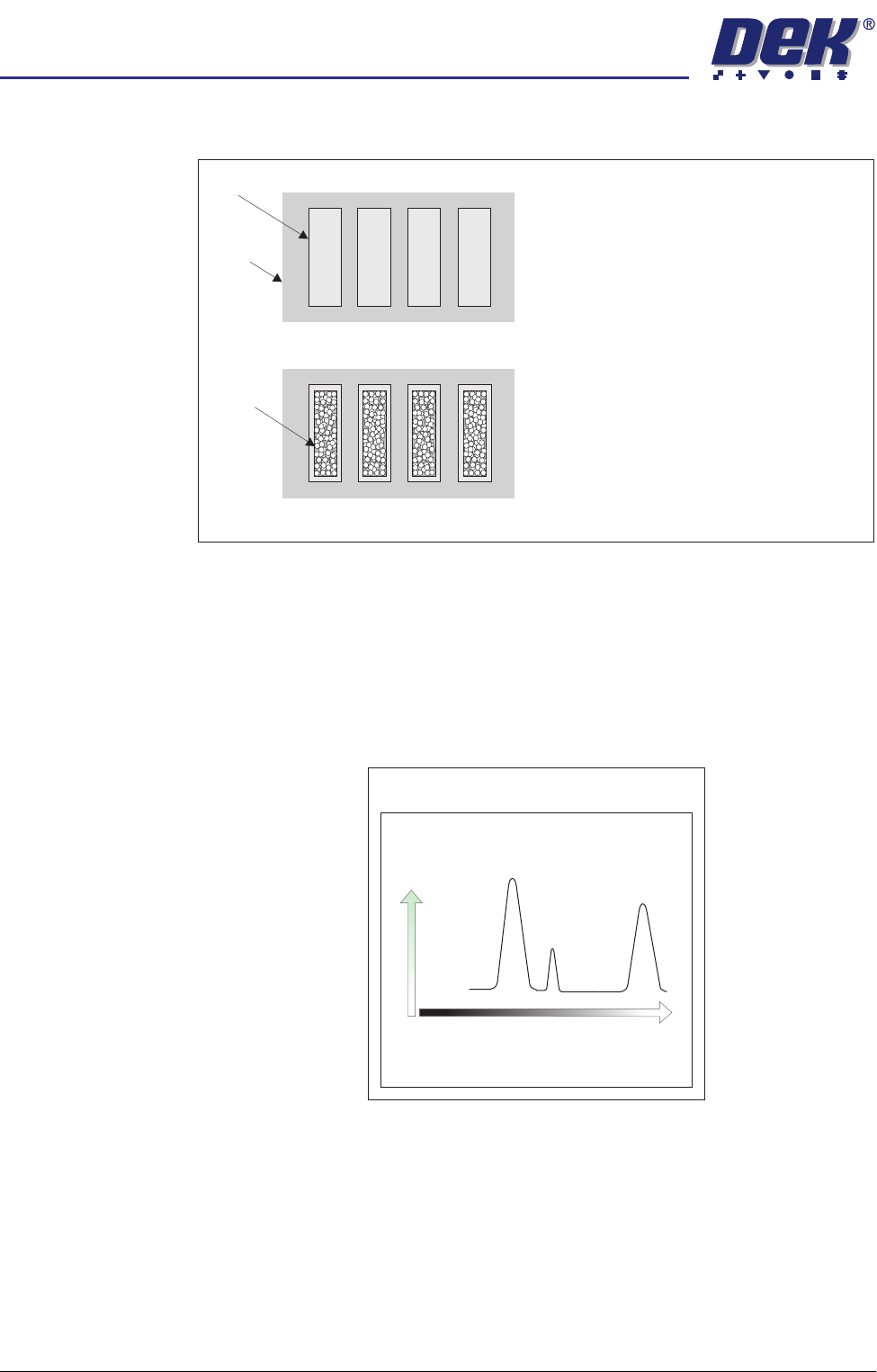
Histogram The vision card analyses the grey scale levels of the pixels that make up the
site image. From this information a histogram is produced, this can be used as
a visual aid to setting up lighting for 2D Inspection.
The pad on a selected board site is
learnt as a reference for comparison
with inspected sites.
Since the area of the pad is learnt,
and the area of paste can be
recognized, any change in pad area
must be paste. Hence the area of
paste present can be calculated with
respect to the aperture size.
Pad
Board
Paste
Clean Board
Paste Present
Board Histogram
Number
of
Pixels
Black
PadBoard
Paste
White
Grey Scale Level
semi automatic
',163(&7,21
02'8/(29(59,(:
Software Version 07SP02 User Manual 7.3
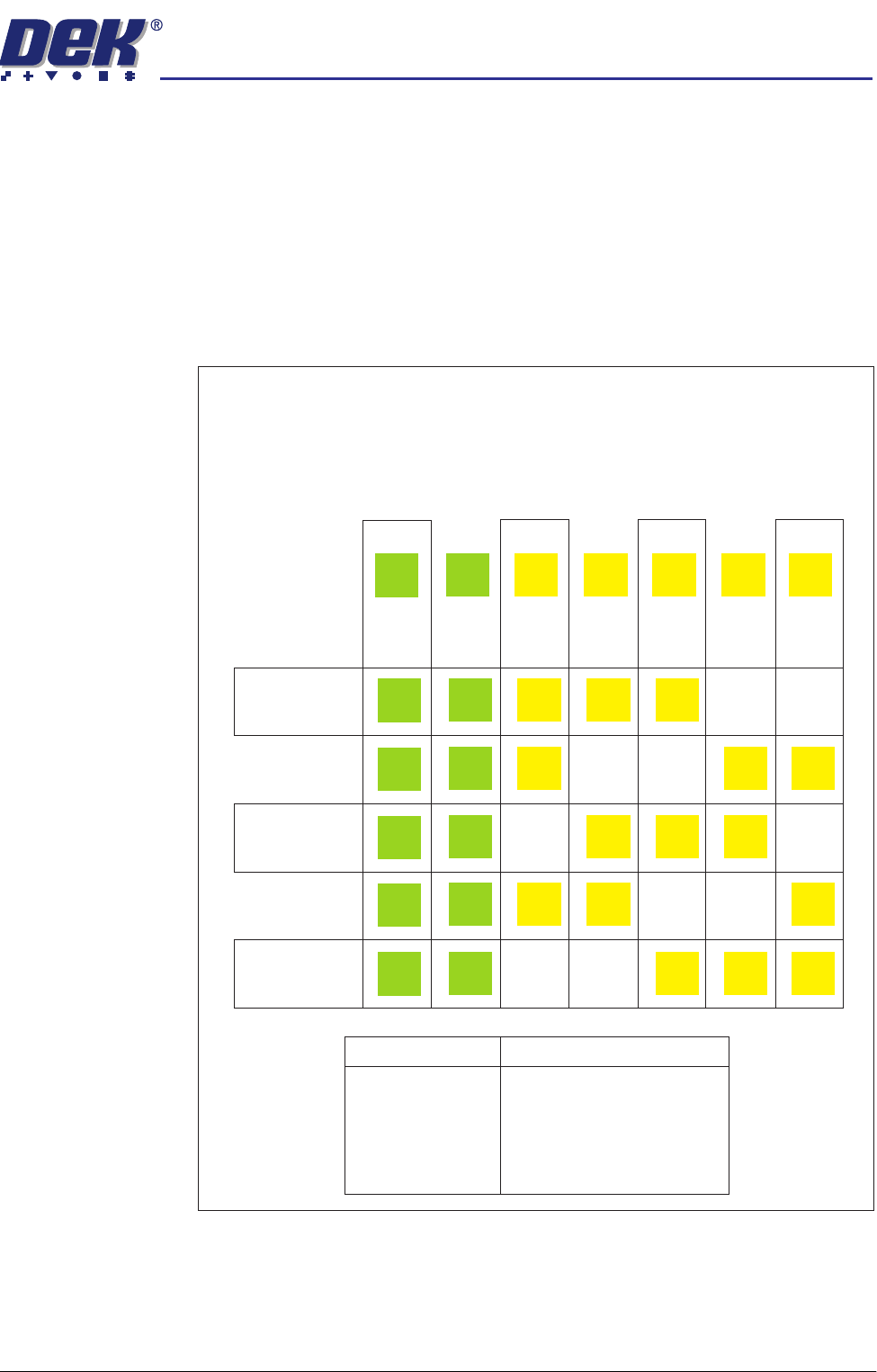
Inspection Cycles During setup, sites are given a priority of either Every Cycle (EC) or General
(G). The amount of sites inspected during each cycle is set using the min sites/
cycle parameter, this must be set to at least the amount of every cycle sites. As
the name suggests, EC sites are inspected every cycle. General sites are
inspected depending on the value of the min sites/cycle parameter and the
number of EC sites as follows:
Number of general sites inspected per cycle = Min sites/cycle parameter - EC
sites.
The general sites are inspected in rotation as shown below.
Figure 7-1 Site Inspection Cycles
min sites / cycle = 5
Cycle 1
Cycle 2
Cycle 3
Cycle 4
Cycle 5
In the example below, seven sites have been setup, with two given the priority
of and five given the priority of .
The min sites/cycle parameter is set at 5. As there are two EC sites, this leaves
three G sites to be inspected at each cycle as shown.
Every Cycle (EC) General (G)
Site 1
EC
EC
EC
EC
EC
EC
Site 2
EC
EC
EC
EC
EC
EC
Site 3
G
G
G
G
Site 4
G
G
G
G
Site 5
G
G
G
G
Site 6
G
G
G
G
Site 7
G
G
G
G
SITES
Cycle 1
Cycle 2
Cycle 3
Cycle 4
Cycle 5
Cycle 6
3, 4, 5
6, 7, 3
4, 5, 6
7, 3, 4
5, 6, 7
process repeats
semi automatic
',163(&7,21
02'8/(29(59,(:
7.4 User Manual Software Version 07SP02
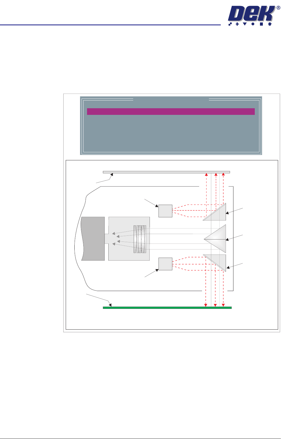
Lighting The lighting level for 2D Inspection is software controlled. For a more detailed
description of the camera and optical unit refer to the Technical Reference
manual - Camera and Vision Systems Module chapter.
The grey camera lighting parameters and functions are shown below. Each
lighting group can be set by the operator to a level between 0 to 15, where 15
is the brightest.
Figure 7-2 Software Controlled Lighting - Grey Camera
Image Recording Selecting Save Image saves the inspection object data using the save object
command. This option is only available if image recording in set preferences is
set to VP or PC disk.
It is recommended to use PC disk only for image recording. When saved the
file name is inspnnnn.im2, where n is an incrementing number.
The first image saved after initialization is insp0001.im2.
NOTE
VP disk saves to the Vision HD if fitted.
Adjustable iIlumination of Board and Stencil
Underside
Stencil
Lamp
Lamp
Board
Prism
Beam Splitter
Mirror
Beam Splitter
Mirror
Camera
Inspection Lighting Parameters
SCREEN VERTICAL
BOARD VERTICAL
WINDOW LEFT
WINDOW TOP
WINDOW WIDTH
WINDOW HEIGHT
8
8
-1.0
-1.5
2.0
2.0
mm
mm
mm
mm