182050 User manual.pdf - 第184页
semi automatic ',163(&7,21 ',163(&7,21 6(78 3 7.10 User Manual Software Ve rsion 07SP02 2D INSPECTION SETUP Prep aration For 2 D Inspection f unctionalit y the machine r equires 2D Inspection i n s…
semi automatic
',163(&7,21
02'8/(29(59,(:
Software Version 07SP02 User Manual 7.9
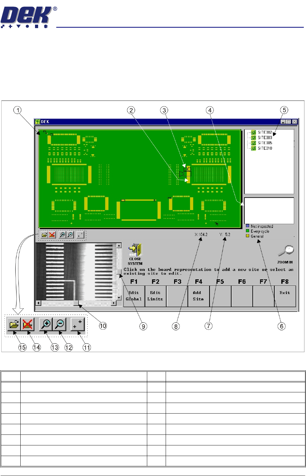
Vision Window The video monitor displays what the camera views, (both board and stencil). A
Region of Interest (ROI) box (red outlined), representing the current boundary
of the site is superimposed on both stencil and board displays.
When movement of the camera is allowed within GUI, scroll bars are displayed
in the vision window to enable fine positioning of the camera unit during site
setup.
Figure 7-5 GUI 2Di Interface (Bitmap File Representation)
Item Description Item Description
1 Board Representation (.bmp or .gbx image file) 9 Vision Window Y Scroll Bar (when available)
2 Inspection Site 10 Vision Window X Scroll Bar (when available)
3 Camera Position Icon 11 Show / Hide Fiducial Positions
4 Inspection Site Parameters 12 Zoom Out on Board Representation
5 Site List 13 Zoom In on Board Representation
6 Site Priority Guide 14 Unload .bmp or .gbx Image file
7 Site Y Coordinates (current mouse position) 15 Load .bmp or .gbx Image file
8 Site X Coordinates (current mouse position)
semi automatic
',163(&7,21
',163(&7,216(783
7.10 User Manual Software Version 07SP02
2D INSPECTION SETUP
Preparation For 2D Inspection functionality the machine requires 2D Inspection in set
preferences to be set to enabled. Carry out the following procedures:
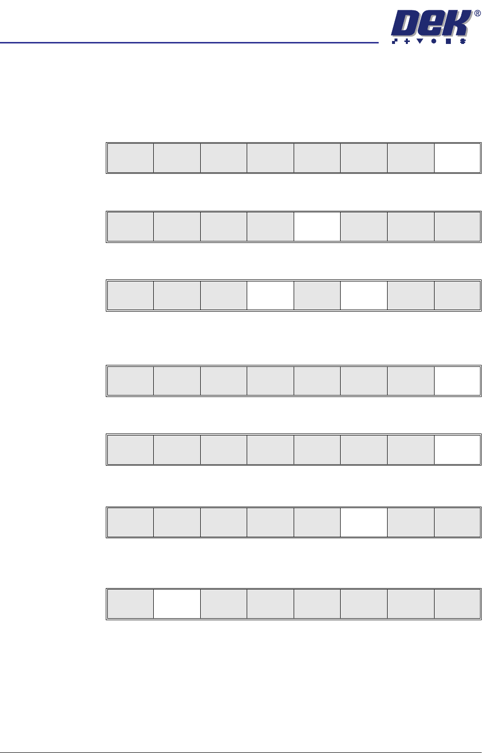
Set Preferences 1. Select Maint.
2. Select Set Prefs.
3. Using the Next and Incr keys, set 2D Inspection to Enabled.
4. Select Exit. The message ‘Printer configuration data file saved’ is
displayed in the message prompt bar above the menu bar.
5. Select Exit.
Load Product File 1. Select Setup.
2. Select Load Data. The message ‘Use keyboard to action product
search’ is displayed in the message prompt bar above the menu bar.
The Load Data File window appears.
Run
Open
Cover
Paste
Load
Clean
Screen
Setup Monitor Maint.
Calibrat
Pressure
Calibrat
Offset
Calibrat
Vision
House
Keeping
S e t
Prefs
Diagnost
Te st
Cycles
Exit
Next Previous Incr. Decr. Exit
Next Previous Incr. Decr. Exit
Calibrat
Pressure
Calibrat
Offset
Calibrat
Vision
House
Keeping
Set
Prefs
Diagnost
Te st
Cycles
Exit
Run
Open
Cover
Paste
Load
Clean
Screen
Setup Monitor Maint.
Mode
Load
Data
Edit
Data
Setup
Squeegee
Change
Screen
Change
Tooling
Change
Language
Exit
semi automatic
',163(&7,21
',163(&7,216(783
Software Version 07SP02 User Manual 7.11
3. Use the Left, Right, Up and Down keys to highlight a product file. If the
product to be setup is a new one, select an existing product file and modify
it, (Edit Data refers).
4. Select Load.
5. Select Exit. The machine loads the product file and trains the fiducials.
Edit Data 1. If the loaded product file is the correct one, go to Step 8. If the file needs to
be modified continue with Step 2.
2. Select Setup.
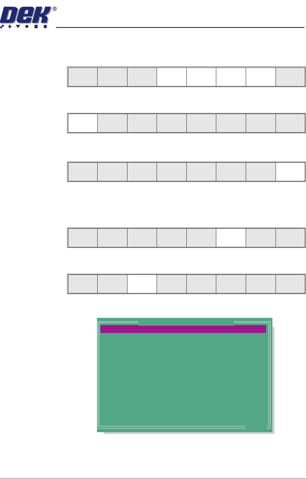
3. Select Edit Data.
The following window is displayed:
4. To change the product name; highlight product name using the Next and
Previous keys. Select Incr. The message ‘Please type in the text, then
press Return’ is displayed, the menu softkeys are blanked out. Type in the
required product name and press Return using the keyboard.
Load
Rebuild
List
Left Right Up Down Exit
Load
Rebuild
List
Left Right Up Down Exit
Load
Rebuild
List
Left Right Up Down Exit
Run
Open
Cover
Paste
Load
Clean
Screen
Setup Monitor Maint.
Mode
Load
Data
Edit
Data
Setup
Squeegee
Change
Screen
Change
Tooling
Change
Language
Exit
PRODUCT NAME
PRODUCT ID
DWELL HEIGHT
DWELL SPEED
SCREEN ADAPTOR
SCREEN IMAGE
CUSTOM SCREEN
BOARD WIDTH
BOARD LENGTH
BOARD THICKNESS
FRONT PRINT SPEED
REAR PRINT SPEED
FLOOD SPEED
PRINT FRONT LIMIT
Dek04
Dek04
30
24
NONE
EDGE
DISABLED
101.5
152.5
1.6
150
150
20
0.0
mm
mm/s
mm
mm
mm
mm/s
mm/s
mm/s
mm
.. more
Edit Current Process Parameters