182050 User manual.pdf - 第194页
semi automatic ',163(&7,21 ',163(&7,21 6(78 3 7.20 User Manual Software Ve rsion 07SP02 How to Add a Site The following pr ocedure detai ls a typical exampl e of creating a new site wit h the GUI b…

semi automatic
',163(&7,21
',163(&7,216(783
Software Version 07SP02 User Manual 7.19
Selecting an
Existing Site
To edit an existing site carry out one of the following procedures:
• Using the mouse left button, select the position of the site on the represen-
tation of the board.
• Using the mouse left button, select the site (or device) name on the devices
and site list.
• Use the Next / Previous buttons on the menu bar.
When an existing site is selected the following GUI display information is
updated:
• Site parameter information.
• Site X and Y coordinates.
• Vision panel camera display image of new site.
semi automatic
',163(&7,21
',163(&7,216(783
7.20 User Manual Software Version 07SP02
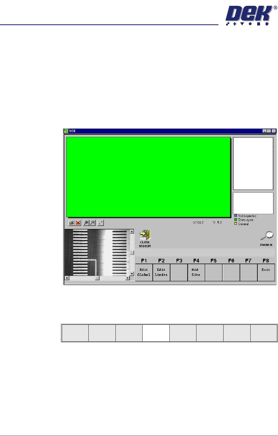
How to Add a Site The following procedure details a typical example of creating a new site with the
GUI board representation displaying the default standard board size format.
NOTE
It may be an advantage to have a board at hand in order to roughly estimate
required site locations.
1. Roughly position the camera to a desired site using the mouse controls and
click on the desired area of the monitor board representation.
2. A camera icon appears at the area selected. The machine camera moves
to the selected area (and board and stencil features are displayed in the
vision window).
3. To position the camera more accurately to the required inspection site,
adjust the X and Y scroll bars displayed in the vision window.
4. Select Add Site.
The site name is automatically appended to a default name, ie SITE001.
If an existing site is selected the menu bar also includes Delete, Edit and
Inspect site function buttons.
NOTE
The operator can rename the new site as required by selecting Incr. or Decr.
and using the keyboard. Press Enter on completion.
Edit
Global
Edit
Limits
Add
Site
Exit
semi automatic
',163(&7,21
',163(&7,216(783
Software Version 07SP02 User Manual 7.21
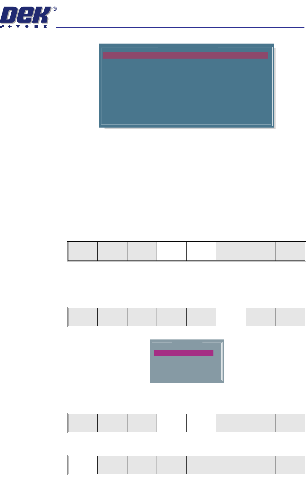
NOTE
The message ‘Use the mouse in the stencil view window to position and
size the site or edit the parameters’ is displayed in the message prompt
bar.
5. Adjust the following edit site parameters to suit the required application:
• Site Priority
• Board Inspect Type
• Site Limit ID
6. Highlight Site Limit ID using the Next and Previous keys.
NOTE
If new inspection file, only default limit is set.
7. Select Incr.
8. Using Next Limit or Previous Limit keys, highlight the limit set required
that was created in either add limits or edit limits.
9. Select Use Limit.
SITE NAME
SITE PRIORITY
SITE BOARD TYPE
SITE LIMIT ID
PASTE SCALING
SITE X COORD
SITE Y COORD
SITE WIDTH
SITE HEIGHT
SCREEN GRAPHIC X
SCREEN GRAPHIC Y
SITE001
EVERY CYCLE
BASIC
DEFAULT
1.00
75.9
111.7
2.00
2.00
0.00
0.00
mm
mm
mm
mm
mm
mm
Edit Site Parameters
Learn
Screen
Light
Setup
Next Previous Incr. Decr. Exit
Learn
Screen
Light
Setup
Next Previous Incr. Decr. Exit
Limit Sets
DEFAULT
COARSE
BGA
QFP
Use
Limit
Next
Limit
Previous
Limit
Exit
Use
Limit
Next
Limit
Previous
Limit
Exit