182050 User manual.pdf - 第197页
semi automatic ',163(& 7,21 ',163(&7,2 16(7 83 Software Version 07SP02 User Manual 7.23 If the gr aphics on the board si de requires adjus ting, use the Incr . Decr . to adjust the X and Y of fsets…
semi automatic
',163(&7,21
',163(&7,216(783
7.22 User Manual Software Version 07SP02
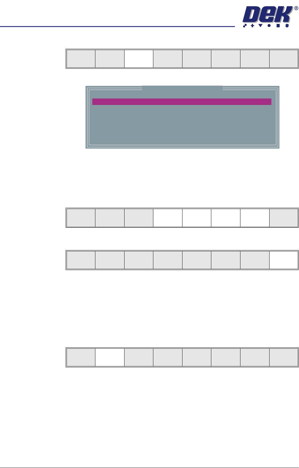
Lighting Setup 1. Select Light Setup.
Figure 7-6 Grey Camera Lighting Parameters
2. Using the Next, Previous, Incr. and Decr. keys, adjust the lighting param-
eters to a level whereby the stencil and board pads are just whiting out,
without blooming, default level 8 is usually adequate for the majority of
setups.
3. Select Exit.
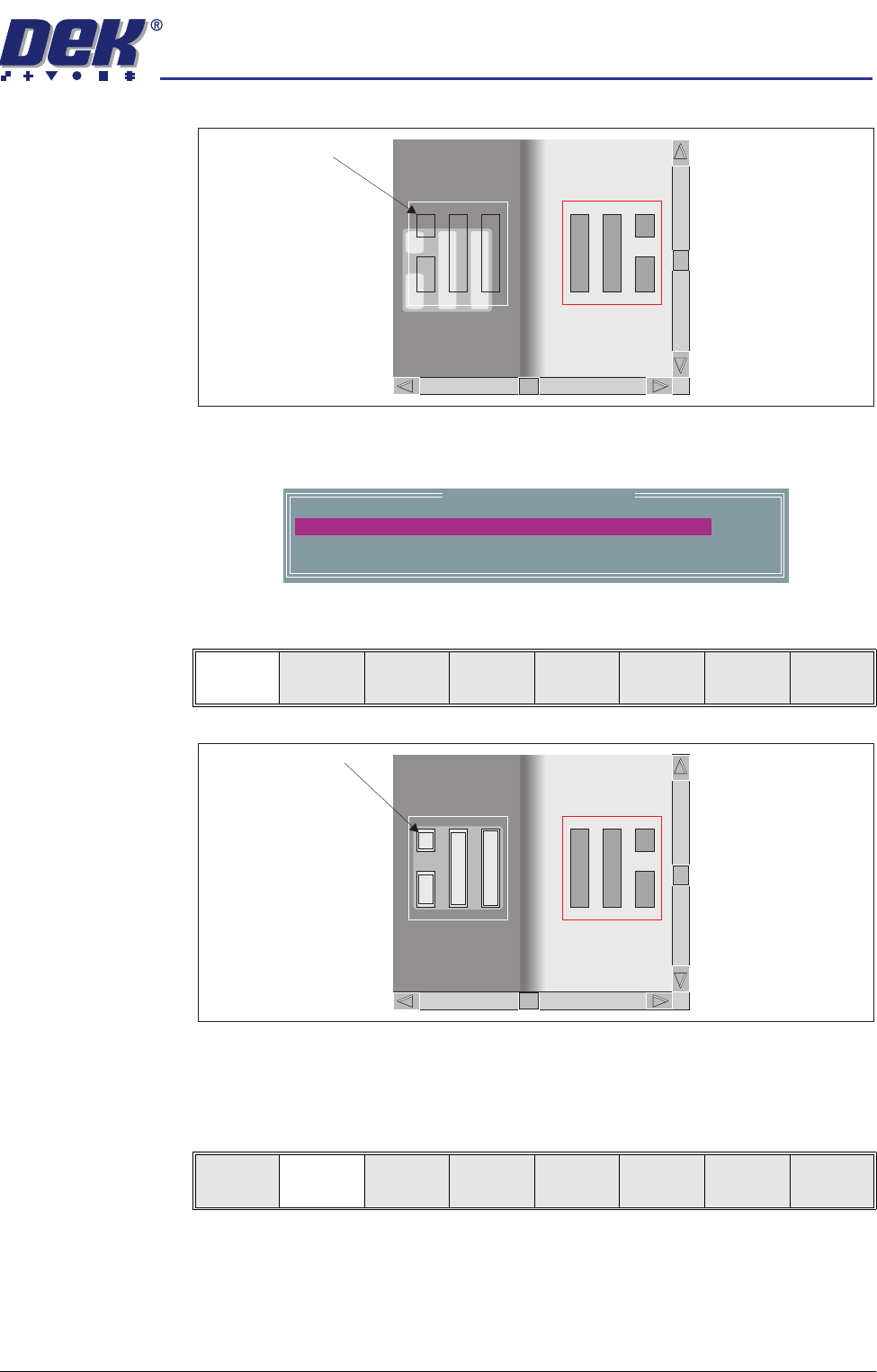
Site Setup 4. Using one of the controls listed, carry out the following:
a. Mouse - Drag and drop the red Region Of Interest box (ROI) to the desired
position.
b. Manual Function Buttons - Next, Previous, Incr. and Decr. keys adjust
the ROI position via the parameters menu.
5. Select Learn Screen.
The message ‘Stencil Learnt. Use the mouse in the board view to align
the board graphic or edit the parameters’ is displayed in the message
prompt bar.
Learn
Screen
Light
Setup
Next Previous Incr. Decr. Exit
Inspection Lighting Parameters
SCREEN VERTICAL
BOARD VERTICAL
WINDOW LEFT
WINDOW TOP
WINDOW WIDTH
WINDOW HEIGHT
8
8
-1.0
-1.5
2.0
2.0
mm
mm
mm
mm
Next Previous Incr. Decr. Exit
Next Previous Incr. Decr. Exit
Add
Site
Learn
Screen
Light
Setup
Next Previous Incr. Decr. Exit
semi automatic
',163(&7,21
',163(&7,216(783
Software Version 07SP02 User Manual 7.23
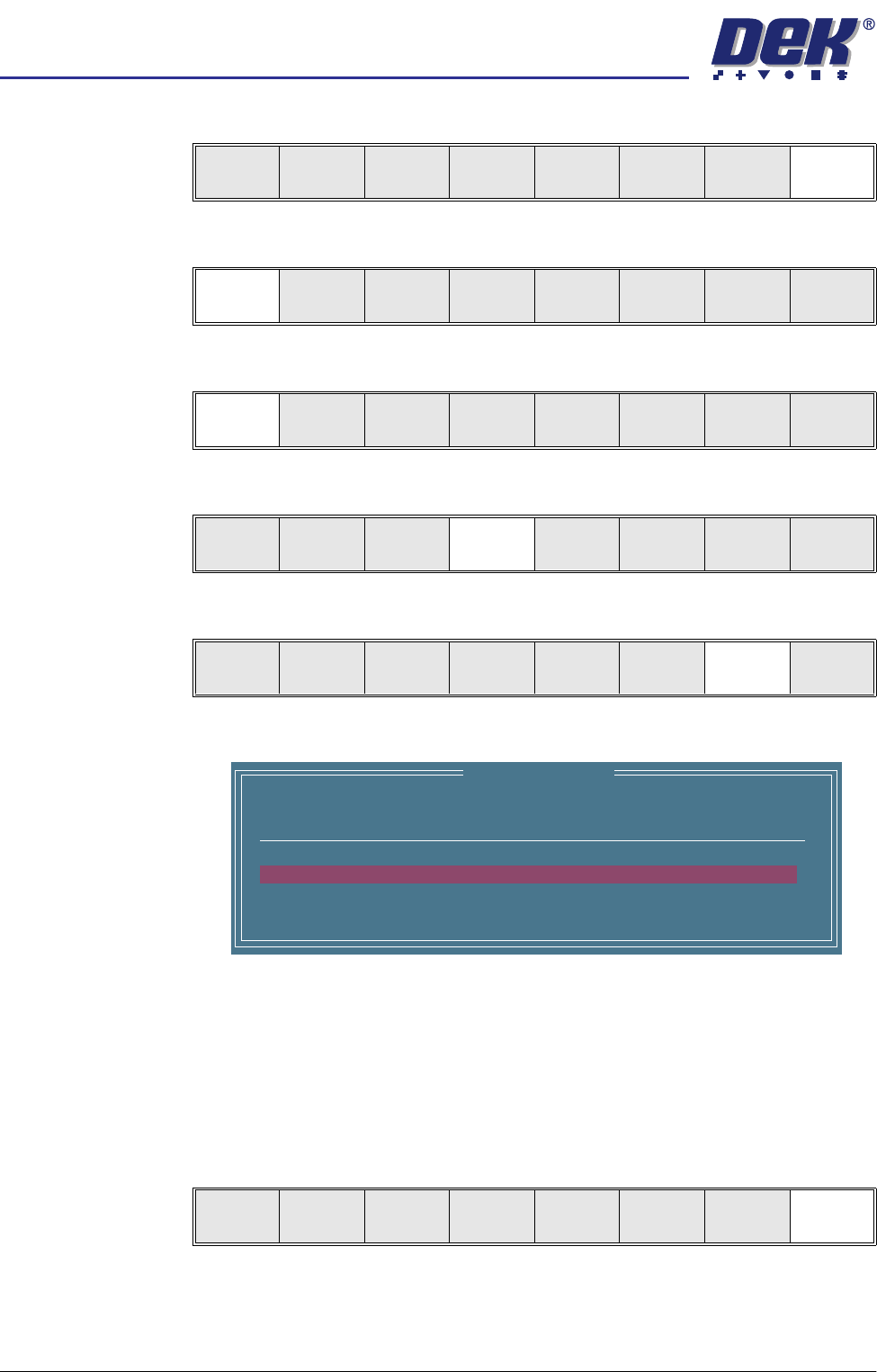
If the graphics on the board side requires adjusting, use the Incr. Decr. to
adjust the X and Y offsets to align the overlay onto the pads.
6. Select Learn Board.
The message ‘Board Learnt’ is displayed in the message prompt bar.
7. If ‘...Board Not Learnt’ is displayed, select Adjust Screen and return to
Step 4.
8. Select Exit.
9. Select Exit.
Image on board does
not coincide with
board pads
Learn Site Parameters
0.0
0.0
mm
mm
BOARD GRAPHIC X
BOARD GRAPHIC Y
Learn
Board
Adjust
Screen
Next Previous Incr. Decr. Exit
Outline of pads are
superimposed on the
board display
Learn
Board
Adjust
Screen
Next Previous Incr. Decr. Exit
semi automatic
',163(&7,21
',163(&7,216(783
7.24 User Manual Software Version 07SP02
Inspect 1. Select Exit.
2. Select Step until board is printed.
3. Select Step until the Inspect Setup menu button is displayed.
4. Select Inspect Setup.
5. Select Inspect Site.
The following window is displayed:
NOTE
A reliable paste present reading is made only when the lighting is set
correctly.
6. Ensure that the inspection results are consistent with the amount of paste
on the pad. If this is correct go to Step 19. If this is incorrect continue with
Step 7.
7. Select Exit.
Edit
Global
Edit
Limits
Delete
Site
Edit
Site
Inspect
Site
Exit
Step
Inspect
Setup
Single Exit
Step Single Exit
Step
Inspect
Setup
Single Exit
Edit
Global
Edit
Limits
Delete
Site
Edit
Site
Inspect
Site
Exit
SITE NAME
Minimum Paste
SITE001
80%
Inspection Results
ALARM
No. Paste Present
1 94%
2 98%
Auto
Scale
Next Previous Exit