182050 User manual.pdf - 第200页
semi automatic ',163(&7,21 ',163(&7,21 6(78 3 7.26 User Manual Software Ve rsion 07SP02 16. Select Exit to remove board from machine . 17. Place a c lean board onto the machine r ails and clean the…
semi automatic
',163(&7,21
',163(&7,216(783
Software Version 07SP02 User Manual 7.25
8. Select Edit Site.
9. Select Light Setup.
10. Adjust the lighting parameters to improve the lighting conditions in the
suspect areas.
11. Select Exit.
NOTE
Record Image button is displayed if Image Recording is enabled in Set
Preferences.
12. If lighting is changed the following menu bar is displayed:
Select the following button to adopt the changes to:
• ‘Apply to Full Set’ - to update only this device
• ‘Apply to All ’ - all learnt sites
• ‘Exit’ - just the current site
13. Select Exit.
14. Select Exit.
15. Select Step to step through inspection routine.
Edit
Global
Edit
Limits
Delete
Site
Edit
Site
Inspect
Site
Exit
Light
Setup
Next Previous Incr. Decr. Exit
Record
Image
Next Previous Incr. Decr. Exit
Apply to
Full Set
Apply to
All
Exit
Light
Setup
Next Previous Incr. Decr. Exit
Edit
Global
Edit
Limits
Delete
Site
Edit
Site
Inspect
Site
Exit
Step
Inspect
Setup
Single Exit
semi automatic
',163(&7,21
',163(&7,216(783
7.26 User Manual Software Version 07SP02
16. Select Exit to remove board from machine.
17. Place a clean board onto the machine rails and clean the stencil (Clean
Screen).
18. Repeat Steps 4 - 8.
19. Select appropriate pad that is considered to be closest to 100% coverage
and select Auto Scale (if required).
Selecting auto scale automatically adjusts the paste scaling value for the
current site, to cause the value of paste present, on the pad currently
selected in the inspection result list, to be reported as 100%. The inspection
results window is updated accordingly. If the calculated value for paste
scaling falls outside the range of allowable values, an error window is
displayed and the paste scaling value is set to the limit nearest the calcu-
lated value. However, if the currently selected paste present value is zero,
no adjustment of the paste scaling value takes place and an error window
is displayed. A prompt is displayed giving the new scaling factor value each
time it is changed. The auto scale button is only present if board inspection
is being performed.
20. Select Exit.
21. Select Exit.
22. Select Step to remove the board from the machine.
23. Clean the board and stencil.
24. Carry out Section How to Add a Site and create all required sites, using the
same lighting parameters as before.
25. On completion carry out Section Inspect.
26. Set required 2D inspect rate and the Min site/cycle parameters in edit global.
27. This completes the 2Di setup. Commence print run in auto mode.
Edit
Global
Edit
Limits
Delete
Site
Edit
Site
Inspect
Site
Exit
Auto
Scale
Next Previous
Save
Image
Exit
Auto
Scale
Next Previous
Save
Image
Exit
Edit
Global
Edit
Limits
Delete
Site
Edit
Site
Inspect
Site
Exit
Step
Inspect
Setup
Single Exit
semi automatic
',163(&7,21
6(7837,36
Software Version 07SP02 User Manual 7.27
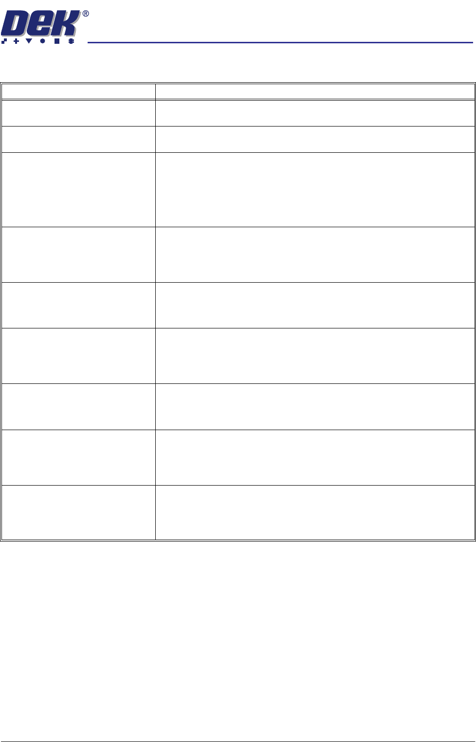
SETUP TIPS
Setup Problem Guide
No inspection setup available Ensure that 2D Inspection is enabled in Set Prefs.
System not inspecting or inspec-
tion cycle not being carried out
The 2D option may be disabled or 2D inspect rate may equal 0.
Order of Inspection If a particular sequence of site inspection is required, the sites should be selected
as every cycle sites and setup in the sequence required.
Every cycle sites are inspected in the order that they were setup.
General sites are inspected in an order that depends on their position and their
inspection sequence cannot be set.
If at a later date a site is edited the sequence is affected.
Stencil and Board - Cleaning Before
Setup
Before 2D Inspection setup, ensure the stencil and board being used have been
thoroughly cleaned and are free of all paste deposits.
If either are not cleaned thoroughly any remaining smearing, partially blocked
apertures or paste on the board may cause an incorrect setup.
Site Area Accuracy Ensure that when setting site parameters (height, width etc.), the site graphic is
placed around the site to give clearance from the apertures and pads thus
preventing other areas being inspected.
Lighting Conditions If the inspection result is not as expected, it is possible that the site was learnt
under different lighting conditions.
This problem may be resolved by re-learning the site under new lighting
conditions, or by the use of paste scaling for paste present adjustment.
Site Quality The sites selected for inspection should be of good quality.
Sites should not have rounded or chamfered edges or uneven or excessive
tinning, this can lead to misleading results when attempting to learn sites.
Sites Being Lost Ensure that both board and stencil have been learnt.
After adjusting board or stencil site parameters always learn both, further editing
can be done at a later stage.
The number of pads must equal the number of apertures for a successful site.
Inspection Alarms too Frequent
and Unnecessary
This may be a symptom of limits being set too tight.
Relax the limits so that results of an acceptable print produce pass or warning, not
alarm, or use the global limit option or limit options to disable the particular limit
checking.