182050 User manual.pdf - 第262页
semi automatic &21680$ %/(5(3/ (1,6+0 (176 352)/2: 8.54 User Manual Software Ve rsion 07SP02 1 1. Using a spatul a, smooth and level the paste to the hei ght of the blades. NOTE Pack any e xcess p aste on the sp atu…
semi automatic
&21680$%/(5(3/(1,6+0(176
352)/2:
Software Version 07SP02 User Manual 8.53
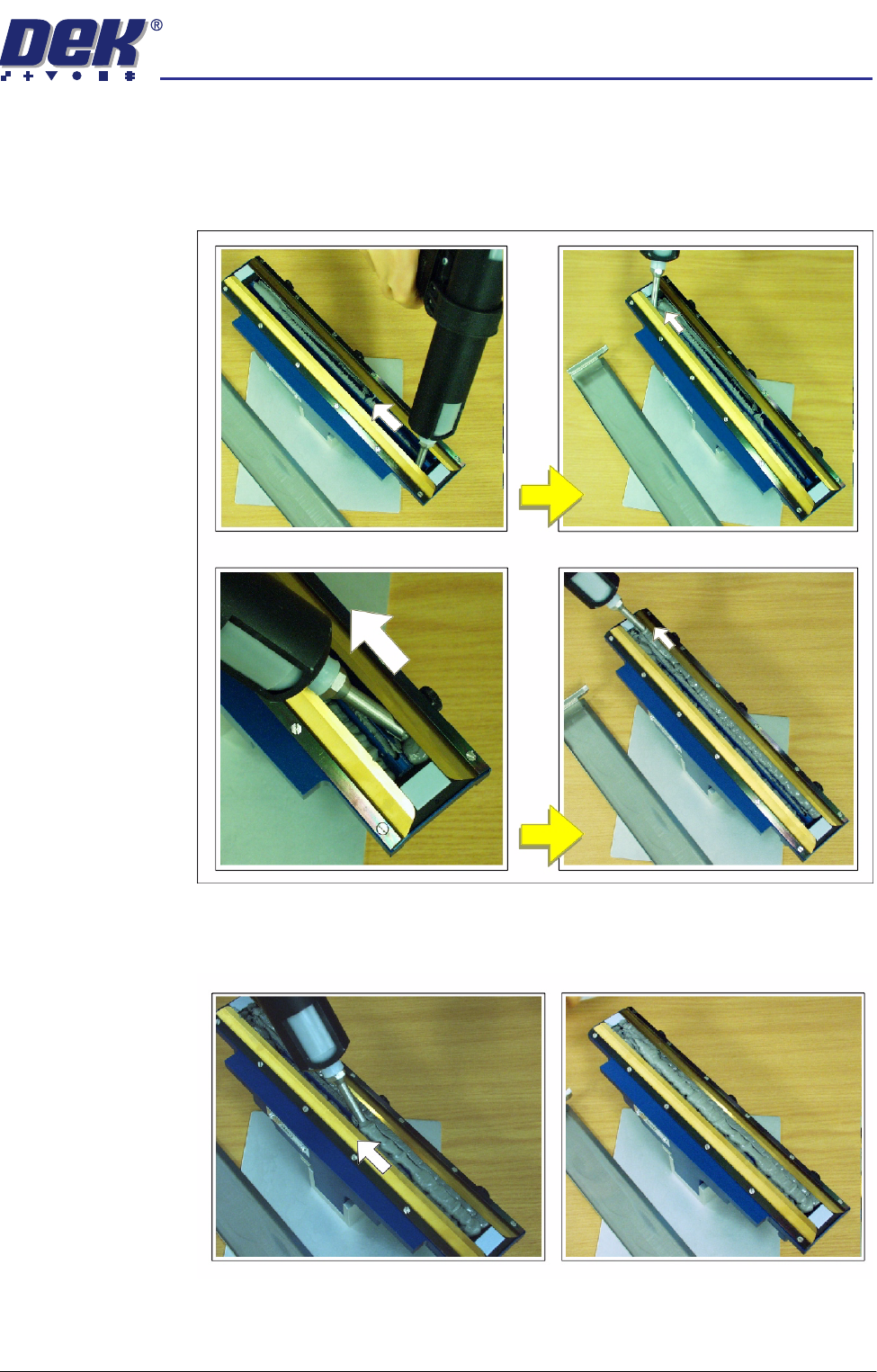
8. Fit the transfer head unit to the maintenance stand and remove the base
cover.
9. Using the recharging unit with long nozzle, fill the length of each side of the
unit, behind the wiper units, (figure below refers).
10. Apply the paste along the length of the centre, between the wipers, filling
paste level with the wiper blade edges, (figure below refers).
semi automatic
&21680$%/(5(3/(1,6+0(176
352)/2:
8.54 User Manual Software Version 07SP02
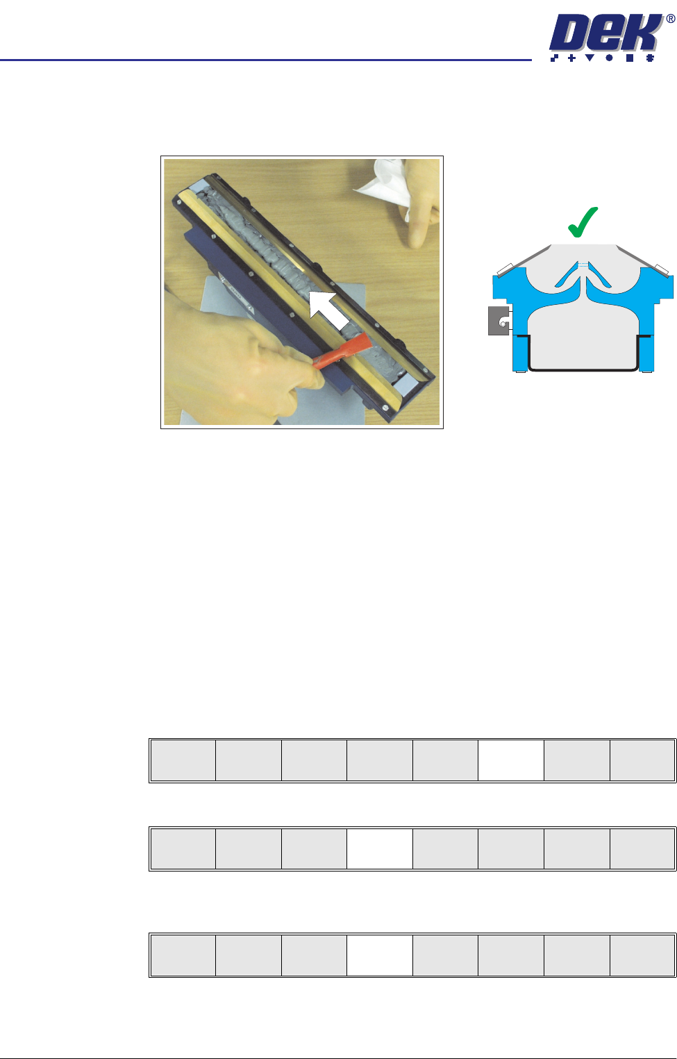
11. Using a spatula, smooth and level the paste to the height of the blades.
NOTE
Pack any excess paste on the spatula between the blades.
12. If necessary clean the wiper blades and skis so that they are not contami-
nated with paste.
NOTE
For effective cleaning, DEK recommend the use of IPA impregnated wipes
(Part No.141150).
13. Fit cover to the unit.
14. Fit the transfer head unit to the ProFlow pressure mechanism on the
machine, (refer to ProFlow chapter in the Technical Reference manual for
detailed information on unit removal/fitting).
Replenishment 1. If the ProFlow unit is in the home position continue with Step 2. If the
ProFlow unit is in the contact position go to Step 19.
2. Select Setup (F6).
3. Select Setup ProFlow (F4).
4. Select Load Cassette (F4). The message ‘Has the ProFlow unit’s base
cover been removed?’ is displayed.
5. If the ProFlow unit’s base cover is still fitted continue with Step 6. If the
ProFlow unit’s base cover has been removed go to Step 12.
=
Run
Open
Cover
Paste
Load
Clean
Screen
Setup Monitor Maint.
Mode
Load
Data
Edit
Data
Setup
ProFlow
Change
Screen
Change
Tooling
Change
Language
Exit
Change
ProFlow
Load
Cassette
Exit
semi automatic
&21680$%/(5(3/(1,6+0(176
352)/2:
Software Version 07SP02 User Manual 8.55
6. Select Remove Cover (F8). The message ‘Open the printer cover and
remove the ProFlow unit’s base cover’ is displayed.
7. Raise the printhead cover.
8. Remove the ProFlow unit’s base cover.
9. Lower the printhead cover.
10. Press the System button.
11. Select Exit (F8).
12. Select Yes (F1). The message ‘The ProFlow unit will be placed in the
REAR envelope’ is displayed.
13. If the ProFlow unit is required to be placed in another envelope continue with
Step 14. If the ProFlow unit is required to be placed in the machine preferred
envelope go to Step 18.
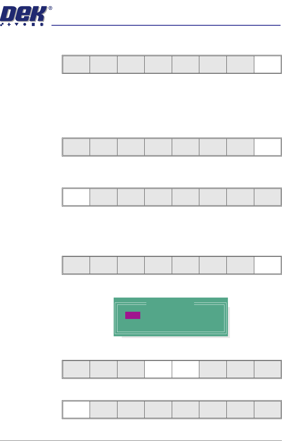
14. Select, Select Another (F8).
The following window is displayed:
15. Use the Next or Previous keys (F4 or F5) to highlight Front.
16. Select Use (F1).
Yes
Remove
Cover
Exit
Yes
Remove
Cover
Proceed
Select
Another
Preferred Envelope
REAR
FRONT
Use Next Previous Exit
Use Next Previous Exit