182050 User manual.pdf - 第27页
semi automatic 0$&+,1 (352*5 $00,1 * 67$*($ 0 $*1( 7,&3,//$56 722/,1* Software Version 07SP02 User Manual 1.17 14. Select Auto Board (F1) . 15. Select Open Cover (F7). 16. Raise t he printhead cov er . 17…
semi automatic
0$&+,1(352*5$00,1*
67$*($0$*1(7,&3,//$56722/,1*
1.16 User Manual Software Version 07SP02
7. Select Save (F2). The message ‘Saving fiducial data - Please wait Board
data file saved’ is displayed.
8. Select Exit (F8).
9. Select Generic Tooling (F7). The print carriage moves to the front of the
machine.
The following window and menu bar is displayed:
NOTE
If contaminated squeegees are fitted, these should be replaced at this point.
10. Select Continue (F1). Cleaner moves to the Home position and the print
carriage moves to the rear of the machine. The message ‘Table at Home
Height’ is displayed.
11. Select Transprt Height (F3). The message ‘Table at Transport Height’ is
displayed.
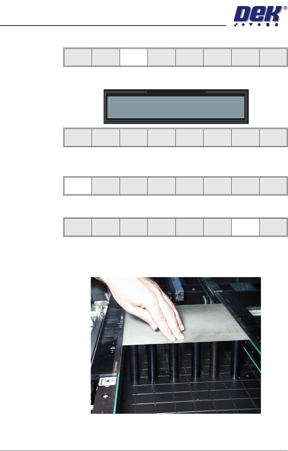
12. Place a board on the input sensor of the transport rail of the machine.
13. Select Load (F1).
Save Next Previous Incr. Decr. Exit
Save Next Previous Incr. Decr. Exit
Adjust
Open
Cover
Home
Cleaner
Board
Stop
Full
Width
Load
Width
Generic
Tooling
Exit
Generic Tooling Warning
WARNING Paste may drip into the machine
Remove Squeegees NOW
Continue
Open
Cover
Exit
Continue
Open
Cover
Exit
Load
Transpr t
Height
Board
Clamps
Change
Screen
Open
Cover
Exit
Load
Vision
Height
Home
Height
Board
Clamps
Change
Screen
Open
Cover
Exit
semi automatic
0$&+,1(352*5$00,1*
67$*($0$*1(7,&3,//$56722/,1*
Software Version 07SP02 User Manual 1.17
14. Select Auto Board (F1).
15. Select Open Cover (F7).
16. Raise the printhead cover.
17. Position the outermost magnetic support pins on the rising table under the
board.
18. Select Board Clamps (F3) to open the clamps.
19. Remove the board from the rails and select Board Clamps (F3) to close the
clamps.
20. Complete the positioning of the magnetic support pins.
21. Select Board Clamps (F3) to open the clamps.
22. Place the board back on the rails over the tooling and select Board Clamps
(F3) to close the clamps.
23. Select Exit (F8).
24. Lower the printhead cover.
25. Press the System button.
26. Select Vision Height (F3). The message ‘Table at Vision Height. Check
Tooling Clearance’ is displayed.
Auto
Board
Manual
Board
Exit
Unload
Vision
Height
Home
Height
Board
Clamps
Change
Screen
Open
Cover
Exit
Board
Clamps
Exit
Board
Clamps
Exit
Board
Clamps
Exit
Board
Clamps
Exit
Board
Clamps
Exit
Unload
Vision
Height
Home
Height
Board
Clamps
Change
Screen
Open
Cover
Exit
semi automatic
0$&+,1(352*5$00,1*
67$*($0$*1(7,&3,//$56722/,1*
1.18 User Manual Software Version 07SP02
27. Select Contact Height (F3).
The following window and menu bar is displayed:
28. Select Continue (F1). The message ‘Table at Contact Height. Check
Tooling Clearance’ is displayed.
29. Select Open Cover (F7).
30. Raise the printhead cover.
31. Check that the setup of the tooling is adequate for the board, adjust as
necessary.
NOTE
If adjustment is required, this can be carried out at Transport Height.
Contact
Height
Transprt
Height
Change
Screen
Open
Cover
Exit
Contact Height Warning
WARNING Check for obstructions between
the Rails and the Screen
Continue
Open
Cover
Exit
Continue
Open
Cover
Exit
Vision
Height
Open
Cover
Exit