182050 User manual.pdf - 第40页
semi automatic 0$&+,1( 352*5$ 00,1* 67$*(& '( ',&$7 ('722/ ,1* 1.30 User Manual Software Ve rsion 07SP02 33. Select Exit (F8). The following windo w and menu bar is displ ayed: 34. Selec…
semi automatic
0$&+,1(352*5$00,1*
67$*(&'(',&$7('722/,1*
Software Version 07SP02 User Manual 1.29
25. Select Contact Height (F3).
The following window and menu bar is displayed:
26. Select Continue (F1). The message ‘Table at Contact Height. Check
Tooling Clearance’ is displayed.
27. Select Open Cover (F7).
28. Raise the printhead cover.
29. Check that the setup of the tooling is adequate for the board, adjust as
necessary.
NOTE
If adjustment is required, this can be carried out at Transport Height.
30. Lower the printhead cover.
31. Press the System button.
32. Select Exit (F8).
Contact
Height
Transprt
Height
Change
Screen
Open
Cover
Exit
Contact Height Warning
WARNING Check for obstructions between
the Rails and the Screen
Continue
Open
Cover
Exit
Continue
Open
Cover
Exit
Vision
Height
Open
Cover
Exit
Exit
semi automatic
0$&+,1(352*5$00,1*
67$*(&'(',&$7('722/,1*
1.30 User Manual Software Version 07SP02
33. Select Exit (F8).
The following window and menu bar is displayed:
34. Select Continue (F1).
35. Select Auto Board (F1). The message ‘Board on rails, remove and
continue’ is displayed.
36. Remove the board from the rails.
37. Select Continue (F1).
38. Go to Stage 7.
Vision
Height
Open
Cover
Exit
Leaving Generic Tooling
WARNING You are about to return
to the Setup Page
Clear all tooling setup
equipment before proceeding
Continue Exit
Continue Exit
Auto
Board
Manual
Board
Continue
Open
Cover
semi automatic
0$&+,1(352*5$00,1*
67$*('08/7,)/(;722/,1*
Software Version 07SP02 User Manual 1.31
STAGE 6D - MULTIFLEX TOOLING
WARNING
BOARD CLAMPS. EXTREME CARE MUST BE EXERCISED WHEN WORKING IN
THE TOOLING AREA OF THE MACHINE TO AVOID INJURY. THE FOILS ON THE
FRONT AND REAR BOARD CLAMPS ARE VERY SHARP.
CAUTION
BOARD CLAMPS.
Care must be taken to ensure that the board clamps are
not damaged when removing or replacing tooling.
NOTE
Setting up the MultiFlex tooling is to be performed off the machine.
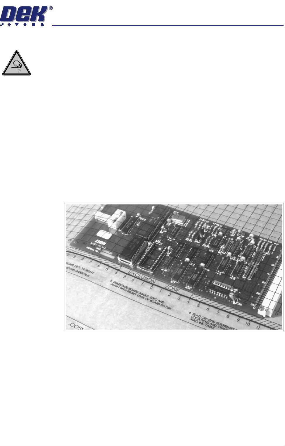
1. Create a box the same size as the board using the side plates.
2. Use the board width and board length dimensions to position the box
correctly.
3. Place the PCB on a flat surface, component side up.
4. Position the acetate template, supplied with the tooling, over the PCB such
that the front edge of the board is aligned with the arrow indicators on the
template. Ensure that the centreline of the board is aligned with the template
zero.