182050 User manual.pdf - 第53页
semi automatic 0$&+,1 (352*5 $00,1 * 67$*( ()2 50)/(; 722/,1* Software Version 07SP02 User Manual 1.43 2. Select C hange T ooling (F6). The print carri age and the under screen cleaner are moved to t he rear .…
semi automatic
0$&+,1(352*5$00,1*
67$*(()250)/(;722/,1*
1.42 User Manual Software Version 07SP02
33. Select Exit (F8).
The following window and menu bar is displayed:
34. Select Continue (F1).
35. Select Auto Board (F1). The message ‘Board on rails, remove and
continue’ is displayed.
36. Remove the board from the rails.
37. Select Continue (F1).
38. Go to Stage 7.
Universal Set Plate Procedure
WARNING
BOARD CLAMPS. EXTREME CARE MUST BE EXERCISED WHEN WORKING IN
THE TOOLING AREA OF THE MACHINE TO AVOID INJURY. THE FOILS ON THE
FRONT AND REAR BOARD CLAMPS ARE VERY SHARP.
CAUTION
BOARD CLAMPS.
Care must be taken to ensure that the board clamps are
not damaged when removing or replacing tooling.
NOTE
1. Ensure that Generic Tooling is set to Enabled in Set Prefs.
2. When using FormFlex, the print gap in the product file must be set to zero.
1. If there is a screen loaded return to Stage 5 to remove the screen.
Vision
Height
Open
Cover
Exit
Leaving Generic Tooling
WARNING You are about to return
to the Setup Page
Clear all tooling setup
equipment before proceeding
Continue Exit
Continue Exit
Auto
Board
Manual
Board
Continue
Open
Cover
semi automatic
0$&+,1(352*5$00,1*
67$*(()250)/(;722/,1*
Software Version 07SP02 User Manual 1.43
2. Select Change Tooling (F6). The print carriage and the under screen
cleaner are moved to the rear.
The Change Tooling Parameters window is displayed:
3. Setting up the board stop position is automatically done using the board
dimensions previously set in the product file. If they need adjustment to re-
position the board stop for any reason, ie any routing on the board edge or
a badly positioned image on the stencil, this can be done now. If adjustment
is necessary continue with Step 4. If adjustment is not necessary go to Step
9.
4. Select Adjust (F1).
5. Use the Next and Previous keys (F4 - F5) to highlight each parameter.
6. Use the Incr. and Decr. keys (F6 - F7), or the forward slash key (/) on the
keyboard, to change the parameter value.
7. Select Save (F2). The message ‘Saving fiducial data - Please wait Board
data file saved’ is displayed.
8. Select Exit (F8).
Mode
Load
Data
Edit
Data
Setup
Squeegee
Change
Screen
Change
Tooling
Change
Language
Exit
Change Tooling Parameters
BOARD WIDTH
BOARD STOP X
BOARD STOP Y
UNDER CLEARANCE
216.0
125.0
142.6
19.0
mm
mm
mm
mm
Adjust
Open
Cover
Home
Cleaner
Board
Stop
Full
Width
Load
Width
Generic
Tooling
Exit
Save Next Previous Incr. Decr. Exit
Save Next Previous Incr. Decr. Exit
Save Next Previous Incr. Decr. Exit
Save Next Previous Incr. Decr. Exit
semi automatic
0$&+,1(352*5$00,1*
67$*(()250)/(;722/,1*
1.44 User Manual Software Version 07SP02
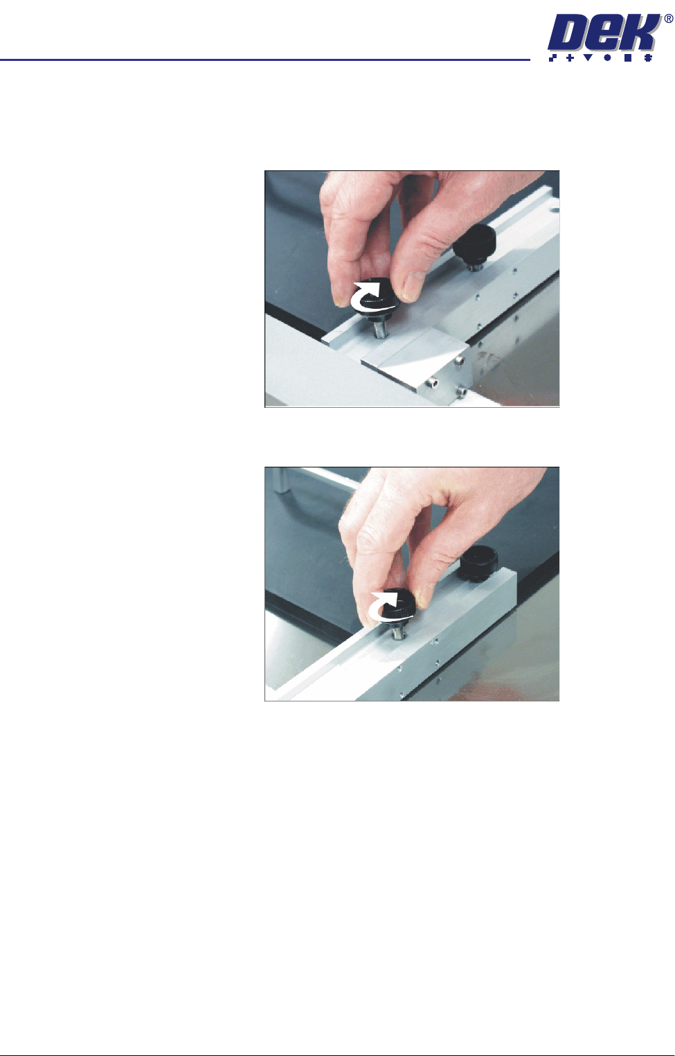
9. Prepare the universal set plate for the current product stencil as follows:
a. For a 20″ I/D stencil, secure the two left hand rod mounts to the plate by
means of the two knurled thumbscrews through the outer and centre
mounting holes in the mount assembly.
b. For a 23″ I/D stencil or larger, secure the rod mounts to the plate using
the centre and inner mounting holes.
10. Position the set plate in the stencil centrally over the image, ensuring the
rods of the rod mounts are in contact with the left hand stencil side.