182050 User manual.pdf - 第55页
semi automatic 0$&+,1 (352*5 $00,1 * 67$*( ()2 50)/(; 722/,1* Software Version 07SP02 User Manual 1.45 1 1. A djust the position of the right hand spring lock assemblies by releasing the two knurled thumbs cre…
semi automatic
0$&+,1(352*5$00,1*
67$*(()250)/(;722/,1*
1.44 User Manual Software Version 07SP02
9. Prepare the universal set plate for the current product stencil as follows:
a. For a 20″ I/D stencil, secure the two left hand rod mounts to the plate by
means of the two knurled thumbscrews through the outer and centre
mounting holes in the mount assembly.
b. For a 23″ I/D stencil or larger, secure the rod mounts to the plate using
the centre and inner mounting holes.
10. Position the set plate in the stencil centrally over the image, ensuring the
rods of the rod mounts are in contact with the left hand stencil side.
semi automatic
0$&+,1(352*5$00,1*
67$*(()250)/(;722/,1*
Software Version 07SP02 User Manual 1.45
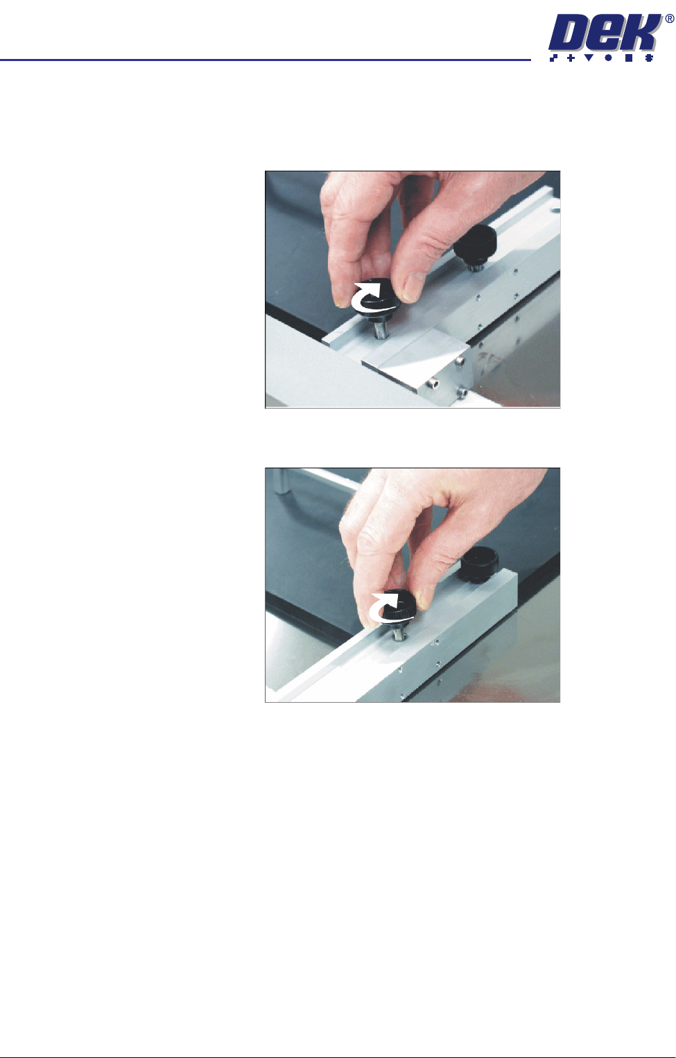
11. Adjust the position of the right hand spring lock assemblies by releasing the
two knurled thumbscrews and sliding the assembly towards the side of the
stencil.
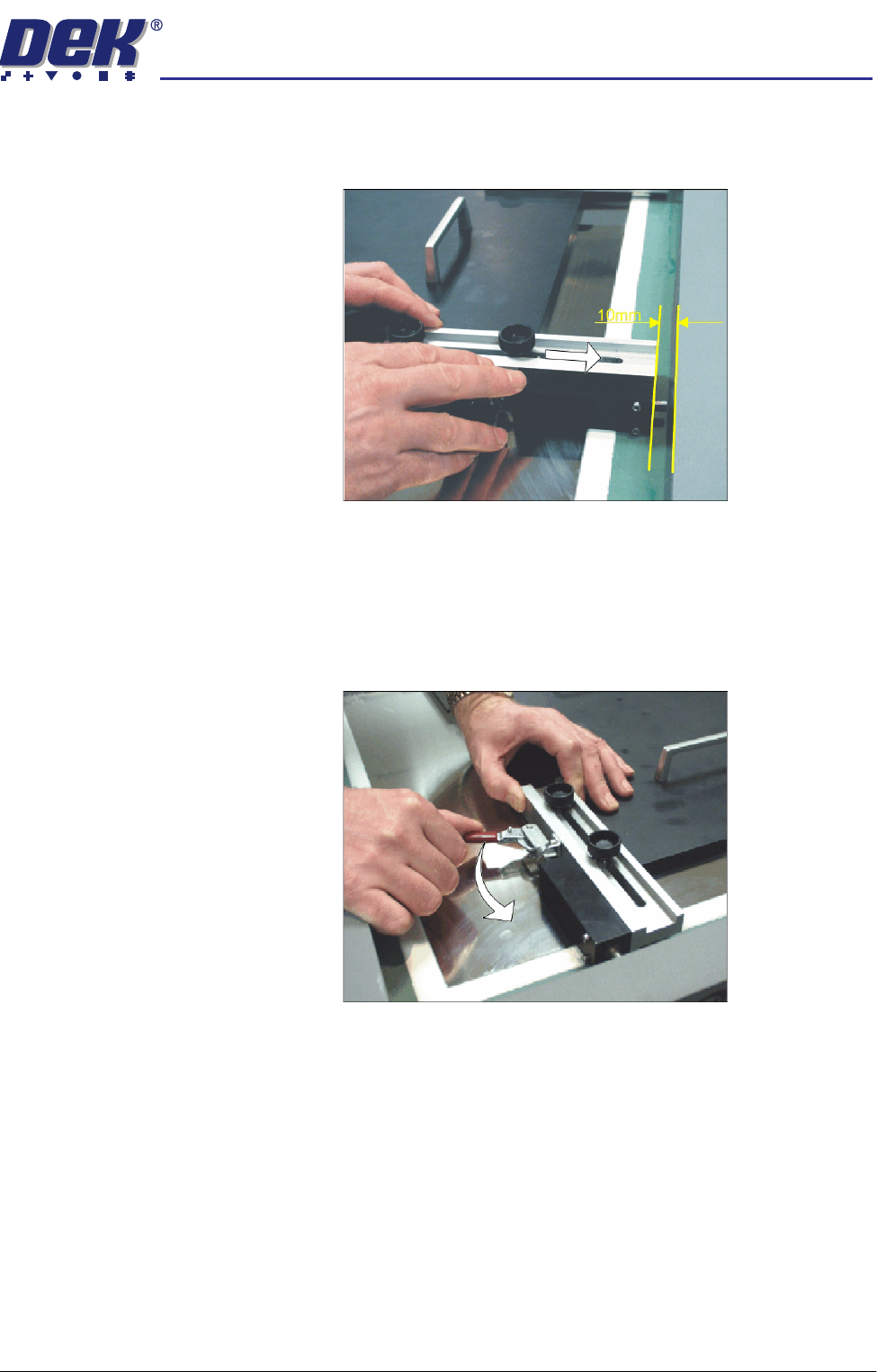
12. Ensure there is a 10mm gap between the stencil side and the end of the
spring lock assembly.
13. Tighten the thumbscrews of the two spring lock assemblies.
14. Ensuring the set plate remains parallel to the stencil sides operate the toggle
clamps to extend the piston shafts against the right hand stencil side. Thus,
clamping the set plate to the inside of the product stencil.
semi automatic
0$&+,1(352*5$00,1*
67$*(()250)/(;722/,1*
1.46 User Manual Software Version 07SP02
15. Select Generic Tooling (F7). The print carriage moves to the front of the
machine.
The following window and menu bar are displayed:
NOTE
If contaminated squeegees are fitted, these should be replaced at this point.
16. Select Continue (F1). Cleaner moves to the Home position and the print
carriage moves to the rear of the machine. The message ‘Table at Home
Height’ is displayed.
17. Select Transprt Height (F3), the message ‘Table at Transport Height’ is
displayed.
18. Place a board at the input sensor of the transport rail.
19. Select Load (F1).
20. Select Auto Board (F1).
21. Select Open Cover (F7).
22. Raise the printhead cover.
Adjust
Open
Cover
Home
Cleaner
Board
Stop
Full
Width
Load
Width
Generic
Tooling
Exit
Generic Tooling Warning
WARNING Paste may drip into the machine
Remove Squeegees NOW
Continue
Open
Cover
No
Continue
Open
Cover
No
Load
Transpr t
Height
Board
Clamp
Change
Screen
Open
Cover
Exit
Load
Vision
Height
Home
Height
Board
Clamp
Change
Screen
Open
Cover
Exit
Auto
Board
Manual
Board
Unload
Vision
Height
Home
Height
Board
Clamp
Change
Screen
Open
Cover
Exit