182050 User manual.pdf - 第59页
semi automatic 0$&+,1 (352*5 $00,1 * 67$*( ()2 50)/(; 722/,1* Software Version 07SP02 User Manual 1.49 c. Using the inner p air of keyway slot s locate the adjuster on the chase and slide the adju ster to the …
semi automatic
0$&+,1(352*5$00,1*
67$*(()250)/(;722/,1*
1.48 User Manual Software Version 07SP02
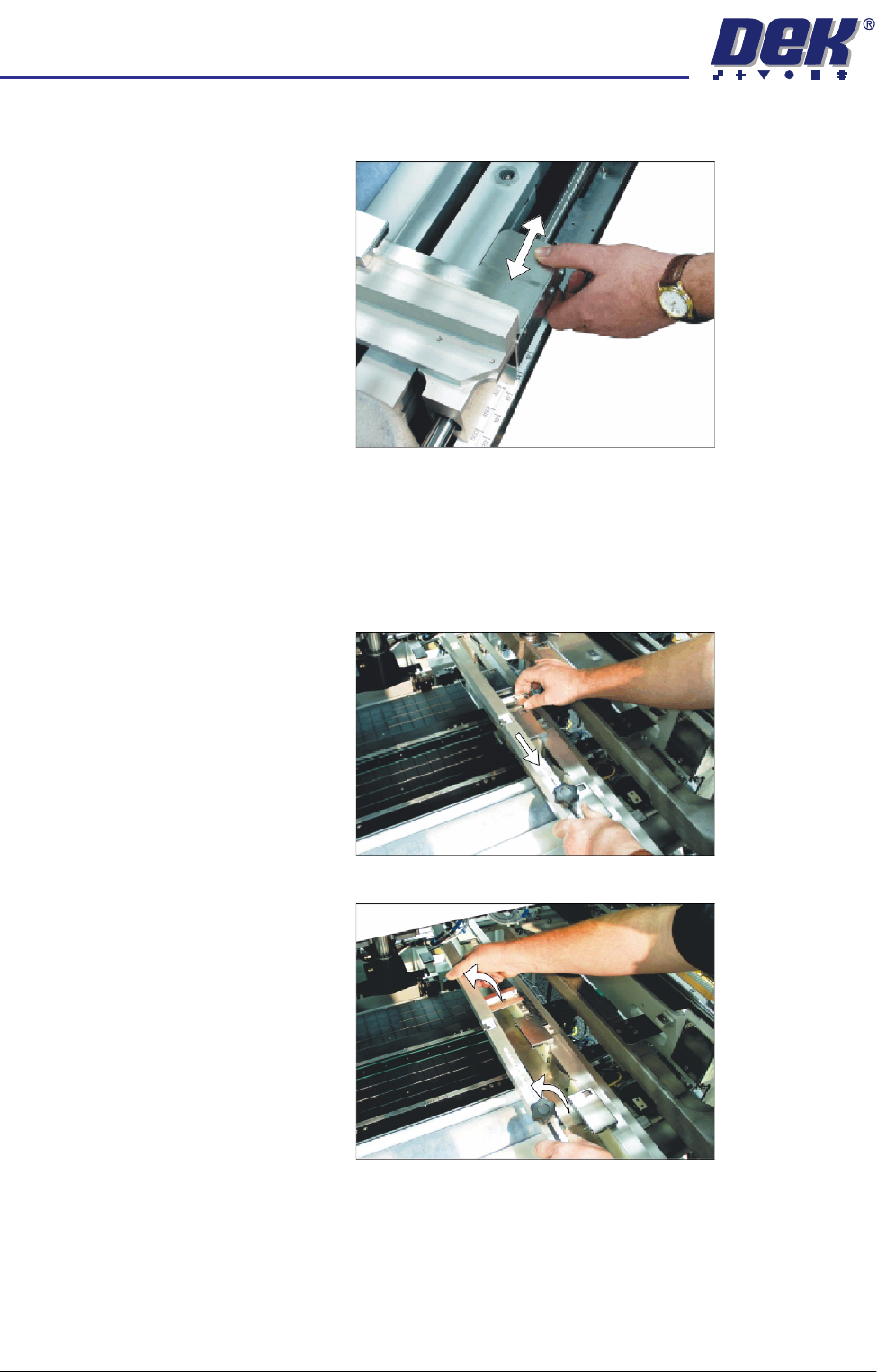
b. Slide the left hand chase rail to the desired position indicated on the
graduated scale.
c. Release the push button valve.
d. Repeat the procedure for the right hand chase rail.
26. If the stencil size is less than 29″ x 29″ the screen depth adjuster position is
to be adjusted as follows:
a. Slide the screen depth adjuster towards the front of the machine.
b. Lift the adjuster clear of the two locating screws.
semi automatic
0$&+,1(352*5$00,1*
67$*(()250)/(;722/,1*
Software Version 07SP02 User Manual 1.49
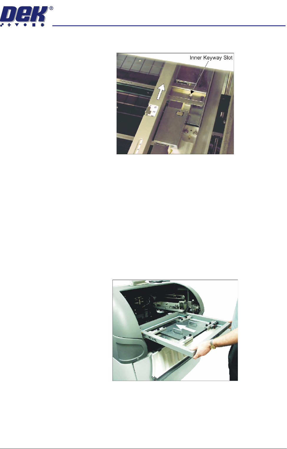
c. Using the inner pair of keyway slots locate the adjuster on the chase and
slide the adjuster to the rear of the machine to lock in place.
27. To adjust the screen depth adjuster for the product carry out one of the
following:
a. ASM, centre or front justified stencil - Set the screen depth adjuster to
Distance to Image. (Distance to Image = the measurement from the rear
face of the stencil frame to the front edge of the board image.)
b. Standard chase, centre justified stencil - Set the screen depth adjuster to
Board Width. (Board Width = the measurement from the rear face of the
stencil frame to the front edge of the board image.)
Standard chase, front justified - Set the screen depth adjuster to 508mm
(20″).
28. Ensuring for the correct orientation of the stencil, load the stencil against the
left hand chase rail and insert until the stencil is fully against the screen
depth adjuster.
29. Toggle screen clamp switch to down position (On) (standard chase only).
30. Lower the printhead cover.
31. Press the System button.
semi automatic
0$&+,1(352*5$00,1*
67$*(()250)/(;722/,1*
1.50 User Manual Software Version 07SP02
32. Select Exit (F8).
33. Select Change Screen (F5).
34. Select Vision Height (F3). The message ‘Table at Vision Height. Check
Tooling Clearance’ is displayed.
35. Select Contact Height (F3).
The following window and menu bar are displayed:
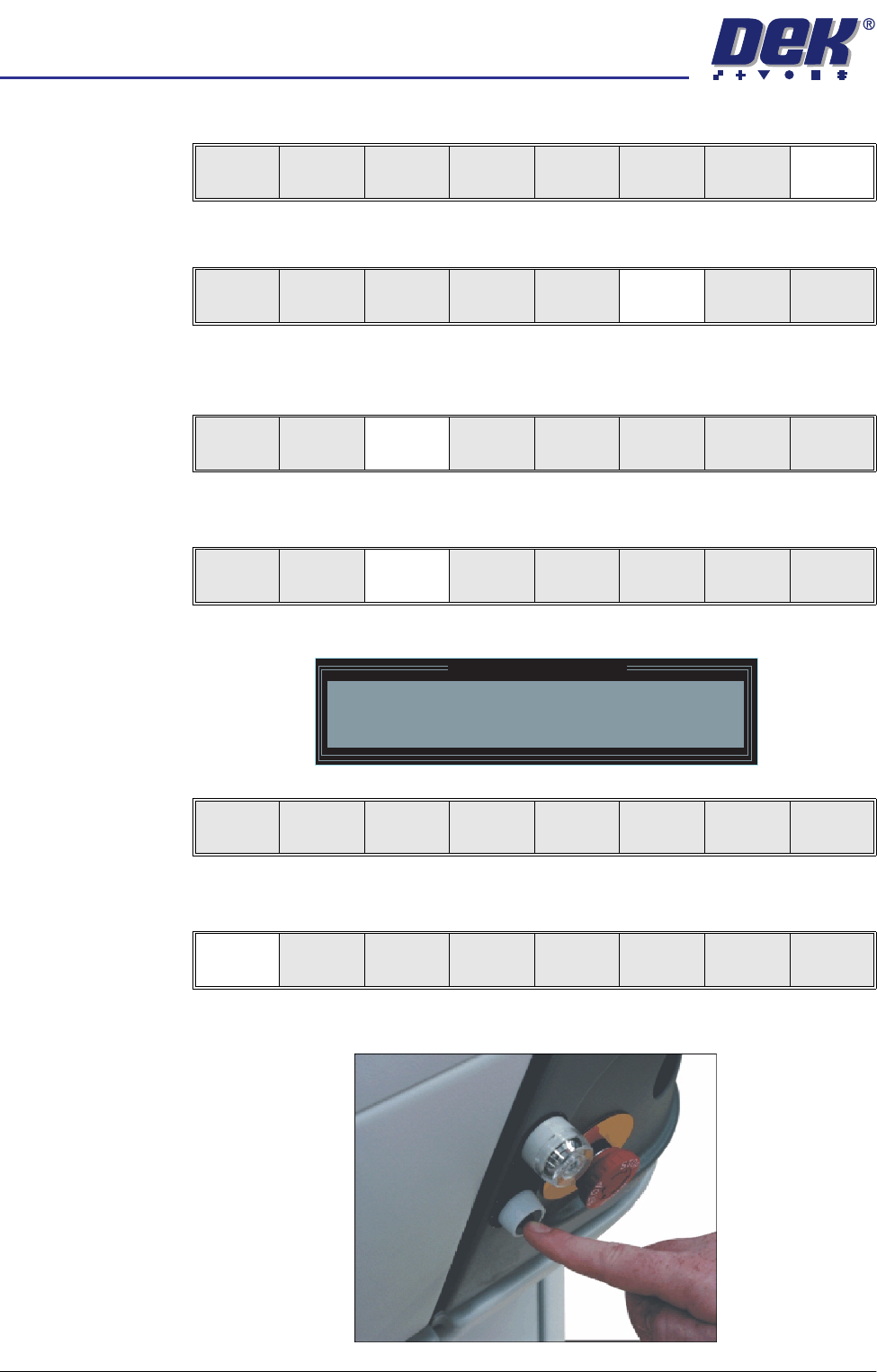
36. Select Continue (F1). The message ‘Table at Contact Height. Check
Tooling Clearance.’ is displayed.
37. Press the operator switch on the front of the machine covers.
Board
Clamps
Exit
Unload
Vision
Height
Home
Height
Board
Clamps
Change
Screen
Open
Cover
Exit
Unload
Vision
Height
Home
Height
Board
Clamps
Change
Screen
Open
Cover
Exit
Contact
Height
Transprt
Height
Change
Screen
Open
Cover
Exit
Contact Height Warning
WARNING Check for obstructions between
the Rails and the Screen
Continue
Open
Cover
Exit
Continue
Open
Cover
Exit