182050 User manual.pdf - 第64页
semi automatic 0$&+,1( 352*5$ 00,1* 67$*( 6& 5((1/2 $' 1.54 User Manual Software Ve rsion 07SP02 b. Lif t the adjuster clear of the two locating screws. c. Using the inner p air of keyway slot s locat…
semi automatic
0$&+,1(352*5$00,1*
67$*(6&5((1/2$'
Software Version 07SP02 User Manual 1.53
STAGE 7 - SCREEN LOAD
1. Raise the printhead cover.
2. If ASM is fitted continue with Step 3. If the standard chase is fitted go to Step
5b.
3. To adjust the width of the chase rails to accommodate the stencil for the
product file loaded, carry out the following:
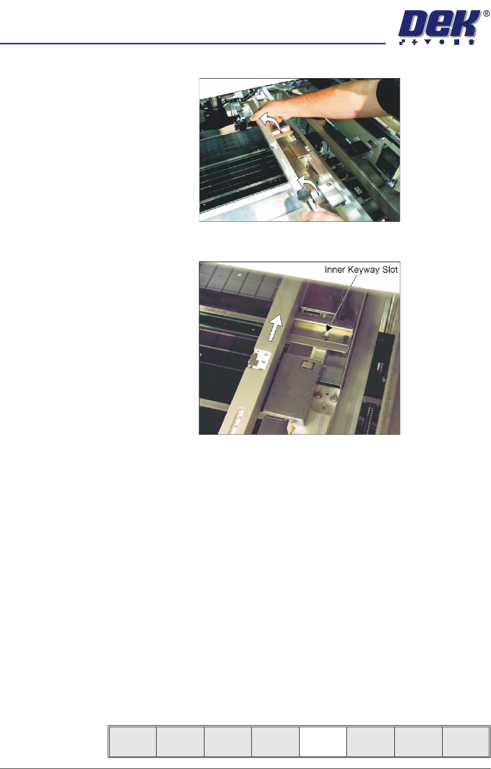
a. Press and hold the left hand chase rail push button valve.
b. Slide the left hand chase rail to the desired position indicated on the
graduated scale.
c. Release the push button valve.
d. Repeat the procedure for the right hand chase rail.
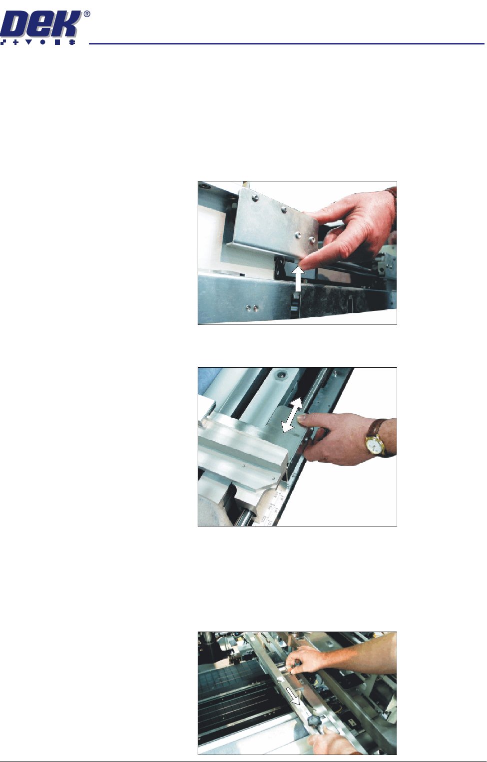
4. If the stencil size is less than 29″ x 29″ the screen depth adjuster position is
to be adjusted as follows:
a. Slide the screen depth adjuster towards the front of the machine.
semi automatic
0$&+,1(352*5$00,1*
67$*(6&5((1/2$'
1.54 User Manual Software Version 07SP02
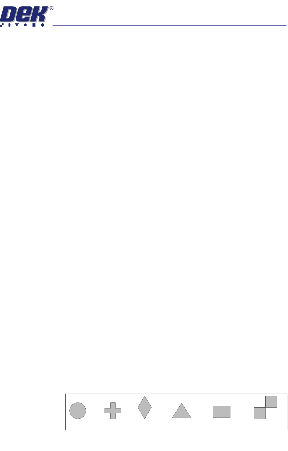
b. Lift the adjuster clear of the two locating screws.
c. Using the inner pair of keyway slots locate the adjuster on the chase and
slide the adjuster to the rear of the machine to lock in place.
5. To adjust the screen depth adjuster for the product carry out one of the
following:
a. ASM, centre or front justified stencil - Set the screen depth adjuster to
Distance to Image. (Distance to Image = the measurement from the rear
face of the stencil frame to the front edge of the board image.)
b. Standard chase, centre justified stencil - Set the screen depth adjuster to
Board Width. (Board Width = the measurement from the rear face of the
stencil frame to the front edge of the board image.)
Standard chase, front justified - Set the screen depth adjuster to 508mm
(20″).
6. Ensuring for the correct orientation of the stencil, load the stencil against the
left hand chase rail and insert until the stencil is fully against the screen
depth adjuster.
7. Toggle screen clamp switch to down position (On) (standard chase only).
8. Lower the printhead cover.
9. Press the System button.
10. Select Change Screen (F5).
Mode
Load
Data
Edit
Data
Setup
Squeegee
Change
Screen
Change
Tooling
Change
Language
Exit
semi automatic
0$&+,1(352*5$00,1*
67$*(9,6,216<67(06(783
Software Version 07SP02 User Manual 1.55
STAGE 8 - VISION SYSTEM SETUP
Introduction The printer uses a vision system to carry out the following:
• Stencil/Board Alignment
• 2D Inspection (optional)
After the board is fed into the machine to the board stop position, the camera
moves into position to view the relative board and stencil features. The
information from these camera images is used by the vision system to calculate
the stencil correction needed. The camera and vision system is also used for
2D Inspection (if enabled), for further information refer to the 2Di chapter in this
manual.
Fiducials A fiducial is an alignment mark which is produced as a part of the artwork of the
board and the stencil. There are normally several of these marks on each
board, some of which are used for board alignment and some for alignment
when placing components on the board. These marks, therefore, should be in
the same relative position on both board and stencil.
The vision system has a library of synthetic fiducials of the most commonly
found shapes. The dimensions of these fiducials can be tailored by the operator
to fit the fiducials on the board and stencil. After the vision system has been
taught these fiducial parameters, it is able to search the field of view of the
camera and recognize any features which resemble these fiducials. The centre
of the fiducial is calculated and used as the point of location.
The vision system conducts a search in the field of view of the camera looking
for any shape that resembles the programmed fiducial. After finding a shape it
is assigned a score comparing its shape and size to the shape and size of the
fiducial in the vision system memory. This score is set between 1 and 999, the
better the fit the higher the score.
NOTE
However, this does not mean that a fiducial score of 999 for example aligns
more accurately than a fiducials score of 700 for example.
This score is used, in conjunction with acceptance parameters set by the
operator, to recognize the fiducial. The available fiducial shapes are:
•Circle
•Cross
• Diamond
• Triangle
• Rectangle
• Double Square
Circle Cross Diamond Triangle Rectangle Double square