182050 User manual.pdf - 第96页
semi automatic 0$&+,1( 352*5$ 00,1* 0(183$5$ 0(7(5 6 1.86 User Manual Software Ve rsion 07SP02 Fiducial 1 Y Coordinate Dist ance of first fiducia l from the front edge of the board. NOTE Refer to Fiducial 1 X Coord…
semi automatic
0$&+,1(352*5$00,1*
0(183$5$0(7(56
Software Version 07SP02 User Manual 1.85
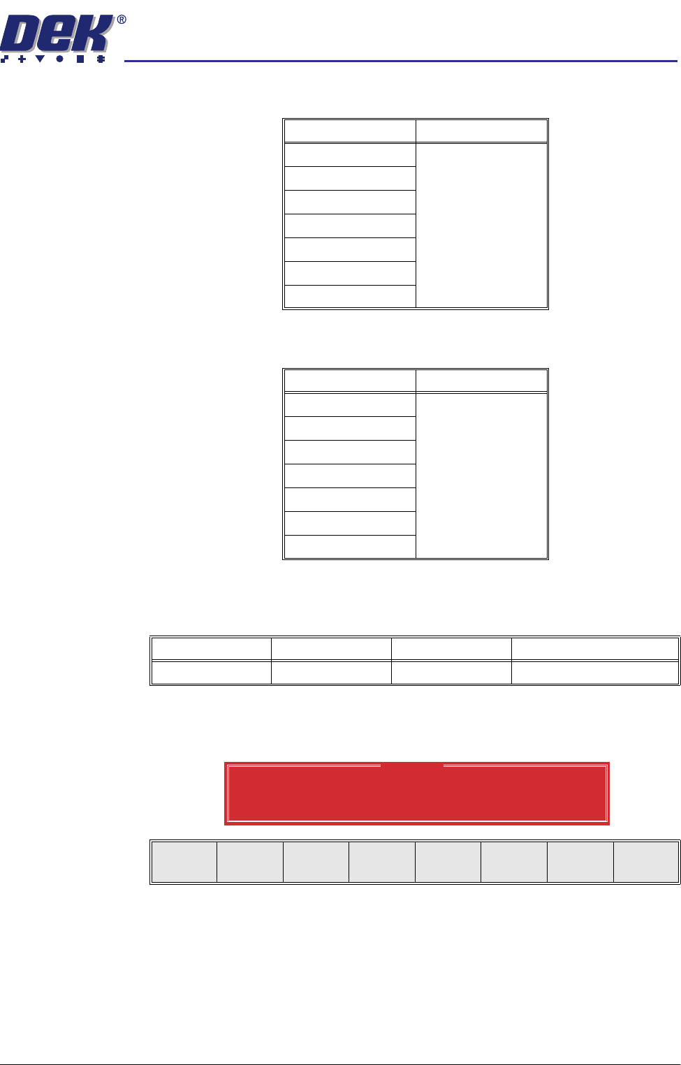
Screen 1 Fiducial
Type
This determines the type of model to be used for this fiducial. Options are:
Screen 2 Fiducial
Type
This determines the type of model to be used for this fiducial. Options are:
Fiducial 1 X
Coordinate
Distance of first fiducial from the right or left hand edge of the board (configura-
tion dependent).
If the current product includes at least one inspection site, changing the value
of the parameter causes the following warning and menu bar to be displayed:
On selecting Apply the alterations to the fiducial positions become effective and
are applied to all inspection sites.
On selecting Abandon Changes the alterations to the fiducial positions are
discarded, the positions of the inspection sites remain unaltered and control is
returned to the initiating sequence.
On selecting Don’t Apply the alterations to the fiducial positions become
effective, but are not applied to the inspection sites.
Model Option Note
Circle
See vision system
Rectangle
Diamond
Triangle
Double Square
Cross
Video Model
Model Option Note
Circle
See vision system
Rectangle
Diamond
Triangle
Double Square
Cross
Video Model
Minimum Maximum Increment Default
1.0mm Board Length 0.1mm 1.0mm
Warning
From the changes made to fiducial positions
do you want a correction to be applied to
all inspection sites?
Apply
Abandon
Changes
Don’t
Apply
semi automatic
0$&+,1(352*5$00,1*
0(183$5$0(7(56
1.86 User Manual Software Version 07SP02
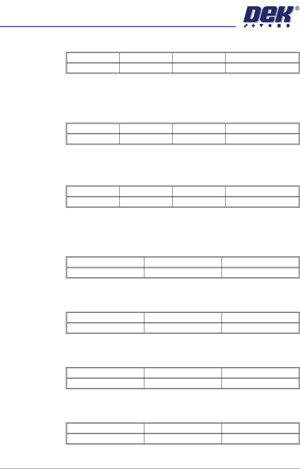
Fiducial 1 Y
Coordinate
Distance of first fiducial from the front edge of the board.
NOTE
Refer to Fiducial 1 X Coordinate warning window information.
Fiducial 2 X
Coordinate
Distance of second fiducial from the right or left hand edge of the board
(configuration dependent).
NOTE
Refer to Fiducial 1 X Coordinate warning window information.
Fiducial 2 Y
Coordinate
Distance of the second fiducial from the front edge of the board.
NOTE
Refer to Fiducial 1 X Coordinate warning window information.
Forward X Offset Programmable offset of the print on the board when printing from the rear.
A positive offset moves the print to the right of the board.
Forward Y Offset Programmable offset of the print on the board when printing from the rear.
A positive offset moves the print to the rear of the board.
Forward Theta
Offset
Programmable offset of the print on the board when printing from the rear.
A positive offset moves the print in a clockwise direction.
Reverse X Offset Programmable offset of the print on the board when printing from the front.
A positive offset moves the print to the right of the board.
Minimum Maximum Increment Default
1.0mm Board Width 0.1mm 1.0mm
Minimum Maximum Increment Default
1.0mm Board Length 0.1mm 1.0mm
Minimum Maximum Increment Default
1.0mm Board Width 0.1mm 1.0mm
Minimum Maximum Increment
-1.0mm +1.0mm 0.004mm
Minimum Maximum Increment
-1.0mm +1.0mm 0.004mm
Minimum Maximum Increment
-1000 arc seconds +1000 arc seconds 2 arc seconds
Minimum Maximum Increment
-1.0mm +1.0mm 0.004mm
semi automatic
0$&+,1(352*5$00,1*
0(183$5$0(7(56
Software Version 07SP02 User Manual 1.87
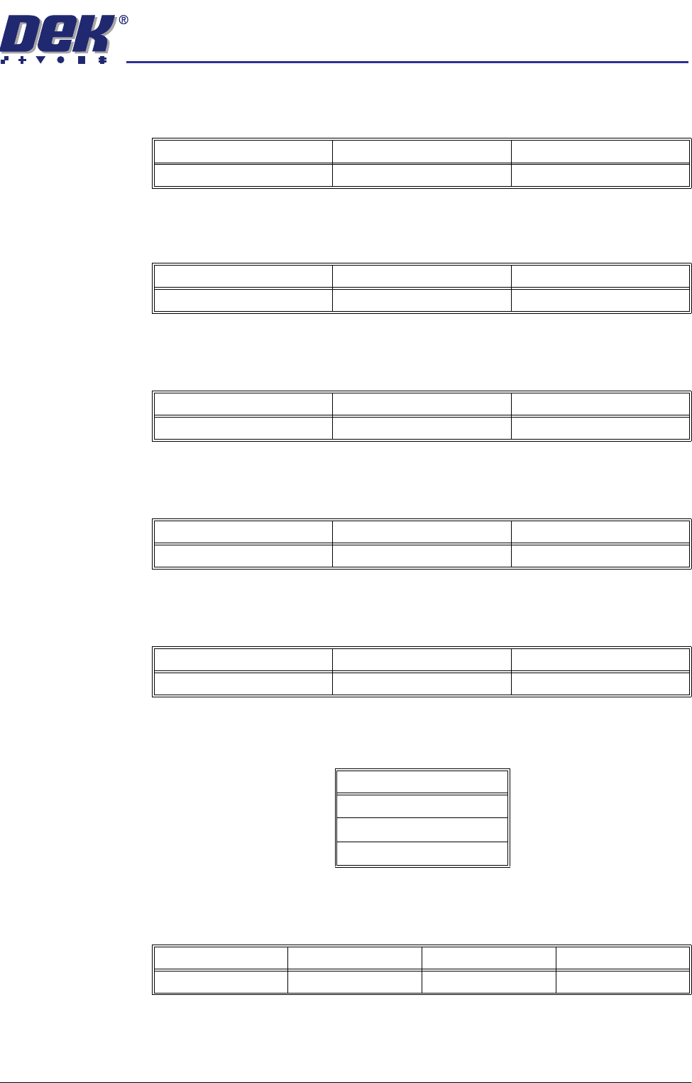
Reverse Y Offset Programmable offset of the print on the board when printing from the front.
A positive offset moves the print to the rear of the board.
Reverse Theta
Offset
Programmable offset of the print on the board when printing from the front.
A positive offset moves the print in a clockwise direction.
Screen X Forward Nominal position of the X front screen actuator which ensures that correspond-
ing stencil and board fiducials can be viewed from a single camera position.
Screen X Rear Nominal position of the X rear screen actuator which ensures that correspond-
ing stencil and board fiducials can be viewed from a single camera position.
Screen Y Axis Nominal position of the Y screen actuator which ensures that corresponding
stencil and board fiducials can be viewed from a single camera position.
Tooling Type This determines which type of board support is to be used with this particular
product. Options are:
Flatten Vacuum
Delay
This parameter determines the duration of vacuum applied whilst the board is
pressed against the underside of the screen with Vac for Flex enabled.
Minimum Maximum Increment
-1.0mm +1.0mm 0.004mm
Minimum Maximum Increment
-1000 arc seconds +1000 arc seconds 2 arc seconds
Minimum Maximum Increment
-20.0mm +20.0mm 0.004mm
Minimum Maximum Increment
-20.0mm +20.0mm 0.004mm
Minimum Maximum Increment
-10.0mm +10.0mm 0.004mm
Options
Magnetic
Vacuum
Vac for Flex
Minimum Maximum Increment Default
0 sec 5 secs 0.1 sec 2 secs