YSM20R_YSM20WR_Mainte_E.pdf - 第114页
3-53 3 Periodic maintenance items e 4 Clean each part of W/U ax es. 1. Press the emergency stop button and then open the machine safety cover . 2. If the machine is carriage type, detach carriage to access to the conveyo…
3-52
3
Periodic maintenance items
5.3 Cleaning and lubricating W-axis
Cleaning and lubricating the ball screw, guide, and hexagon spline of W-axis and U-axis (for YSM20R dual-
stage type) are required once a year. See "Chapter 5 Lubrication points" for details about lubrication points.
Note that the lubrication procedure differs among YSM20R Dual-stage type, YSM20R/YSM20WR Single-lane
type, and YSM20WR Dual-lane type. The following describes each lubrication procedure.
5.3.1 YSM20R Dual-stage: Cleaning and lubricating W/U axes
The following describes the cleaning and lubrication procedure of W-axis and U-axis of YSM20R dual-stage type.
1
Read the desired board data.
TIP
The push-up units of both stage 1 and 2 can be moved
by reading the board data.
2
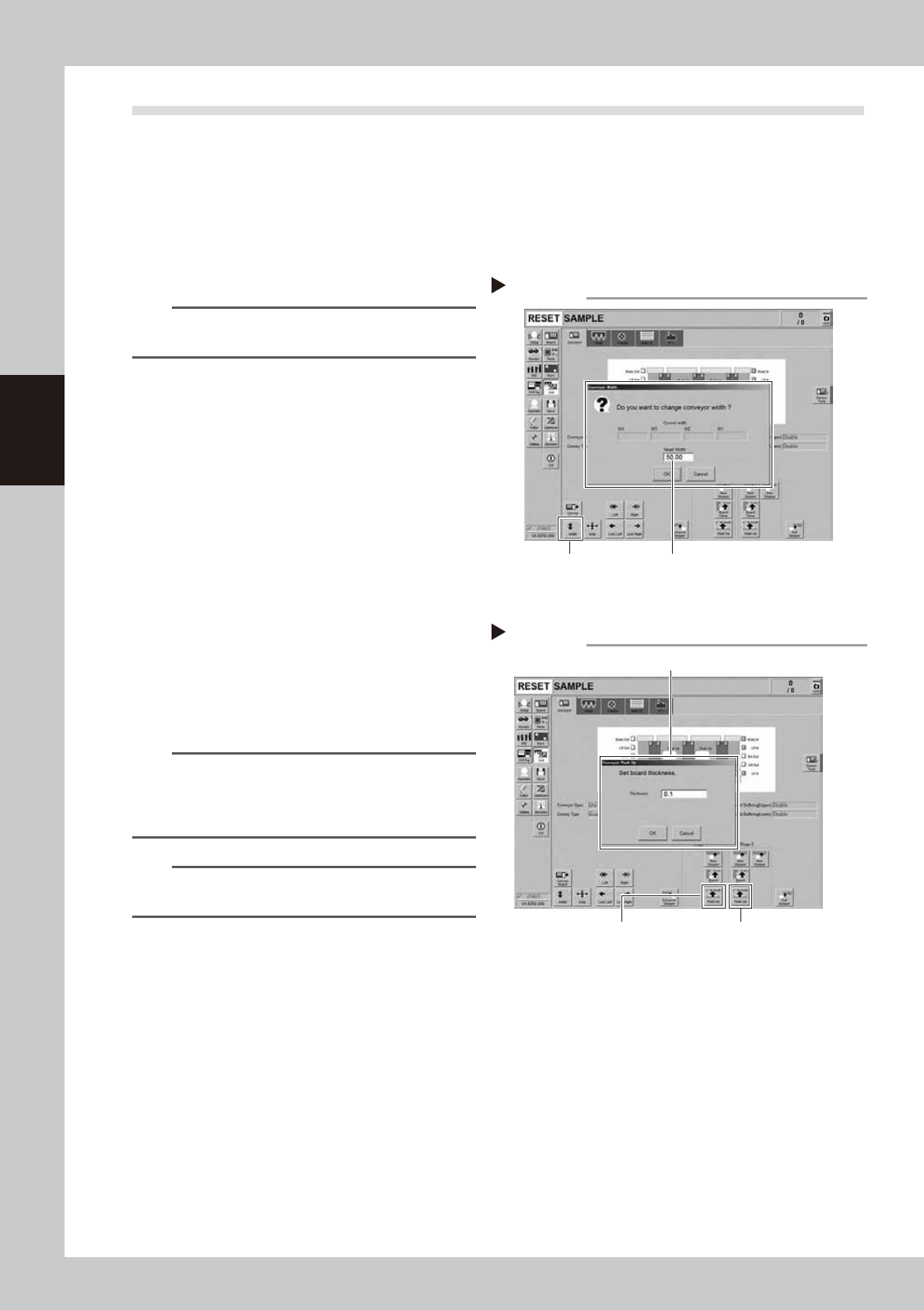
Change the conveyor width to the
minimum width.
1. Press the [Width] button on the [Unit]
- [Conveyor] screen to display the
"Conveyor Width" screen.
2. Enter the minimum conveyor width "50
mm" in the "Target Width" box and press
the [OK] button. The conveyor width is
changed to the specified width.
3
Raise the push-up unit.
1. Press the [Push Up] button to display the
"Conveyor Push Up" screen.
2. Enter "0.1 mm" in the "Thickness" box and
press the [OK] button. The push-up unit is
raised.
3. Raise the push-up units of stage 1 and 2
following the procedure above.
n
NOTE
If the board size X of the board data selected in Step 1
is over 380 mm, the [Push Up] button on the upstream is
grayed out. If raising the push-up unit of downstream,
that of upstream is also raised.
n
NOTE
It is convenient to access to the U-axis guide and ball
screw by raising the push-up unit.
Change conveyor width to minimum
Step 2
[Width] button Enter “50 mm”.
54306-KMK-00
Raising push-up unit
Step 3
Stage 1
[Push Up] button
Enter “0.1 mm”.
Stage 2
[Push Up] button
54307-KMK-00
3-53
3
Periodic maintenance items
e
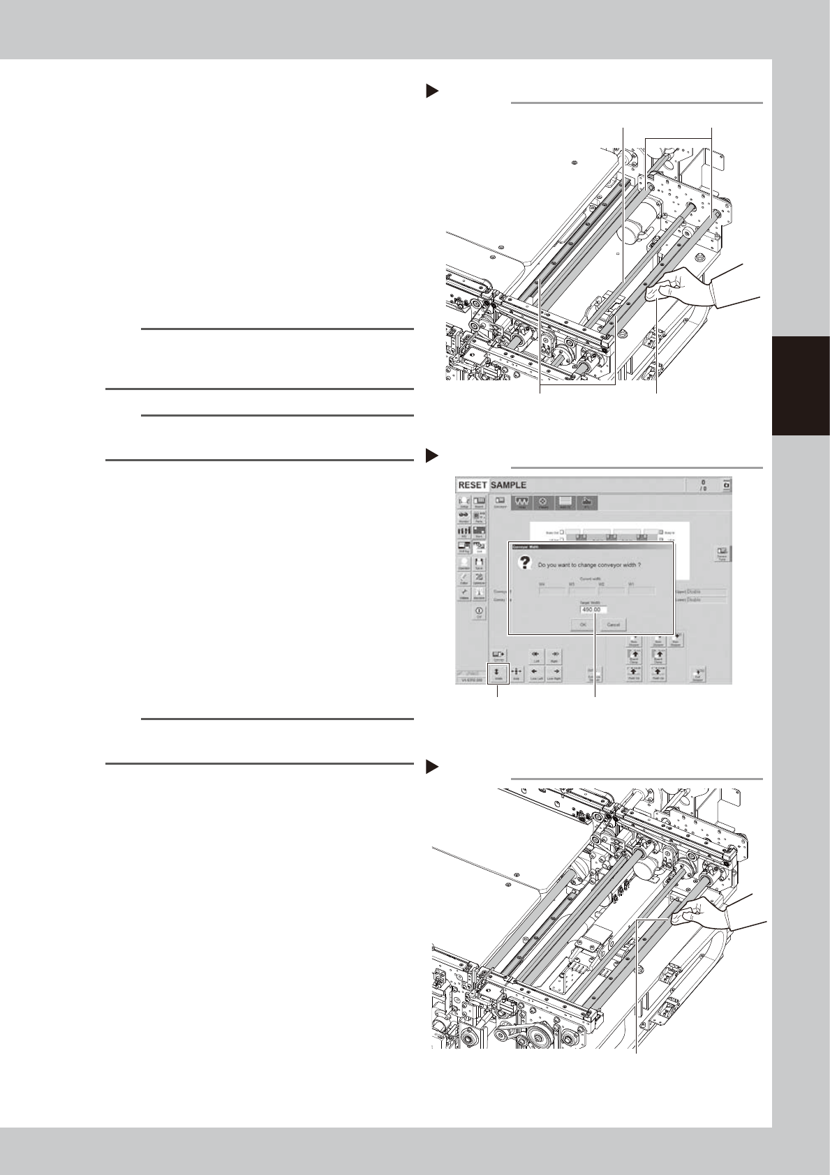
4
Clean each part of W/U axes.
1. Press the emergency stop button and
then open the machine safety cover.
2. If the machine is carriage type, detach
carriage to access to the conveyor.
3. Take off all accessories susceptible to the
magnetic fields, such as a wristwatch
and/or magnetic ID card.
4. Wipe the old grease and soiling on entire
areas of 8 ball screws, 6 guides , and 4
hexagon splines of the W and U axes with
lint-free cloth.
n
NOTE
Carefully wipe the lead grooves of the ball screw and
guide rail during the cleaning. Additionally, make sure
that any dirt is not produced after wiping.
n
NOTE
See "Chapter 5 Lubrication points" for the positions and
quantities of ball screw, guide, and hexagon spline.
5
Change the conveyor width to the
maximum width.
1. Close the machine safety cover and
cancel the emergency stop. Attach the
carriage if the machine is the carriage
type.
2. Press the [Width] button to display the
"Conveyor Width" screen.
3. Enter the maximum value of the
conveyor width of dual-stage type "490
mm" in the "Target Width" box and press
the [OK] button. The conveyor width is
changed to the specified width.
TIP
The push-up unit is lowered automatically by changing
the conveyor width.
6
Raise the push-up unit.
Raise the push-up unit following Step 3.
e
7
Wipe off remaining grease.
1. Press the emergency stop button and
then open the machine safety cover.
2. Detach the carriage if the machine is the
carriage type.
3. Wipe off remaining grease describes in
Step 4 with lint-free cloth.
Cleaning W-axis and U-axis
Step 4
Ball screw
Guide
Hexagon spline shaft
Cloth
53369-KMK-00
Cleaning W-axis and U-axis 2
Step 7
Wipe off remaining grease.
53370-KMK-00
Changing conveyor width to maximum
Step 5
[Width] button Enter “490 mm”.
543108-KMK-00
3-54
3
Periodic maintenance items
8
Apply grease to ball screw and
hexagon spline.
Apply the specified grease (NSL) with finger
uniformly over the hexagon spline shaft
surface and ball screw surface and groove.
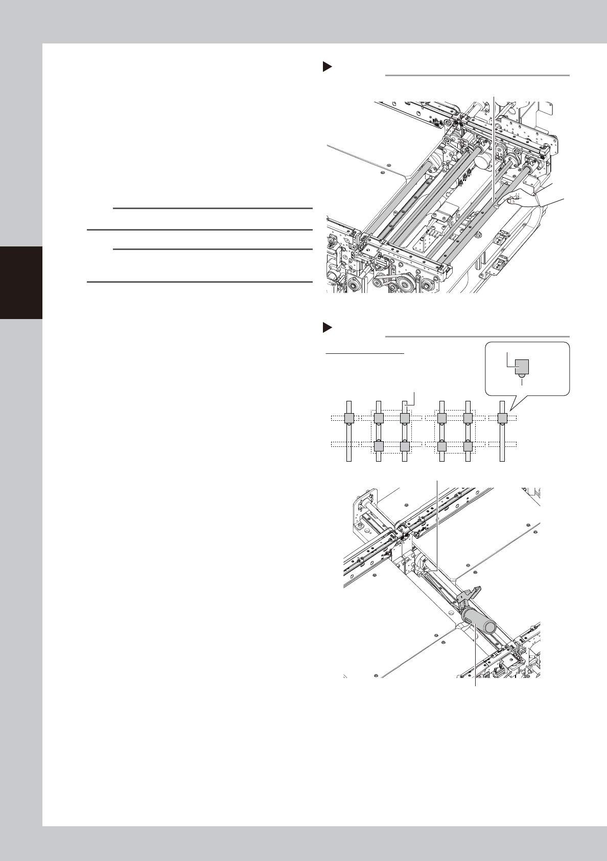
9
Apply grease to the guide.
Apply grease to the guide with grease gun.
Inject the specified grease (NSL) to the
grease nipple of the guide with a grease
gun (bent type nozzle).
n
NOTE
Apply grease until the new grease oozes from the gap.
n
NOTE
See "Chapter 5 Lubrication points"for the positions and
quantity of the guide grease nipple.
Applying grease to ball screw/hexagon spline
Step 8
Grease (Apply uniformly.)
53371-KMK-00
Applying grease to guide
Step 9
Grease nipple
Grease gun (30°-bent type)
Position of grease nipple
Grease nipple
Linear guide block
Guide
W1W2W3
W4
53372-KMK-00