YSM20R_YSM20WR_Mainte_E.pdf - 第123页
3-62 3 Periodic maintenance items 5.4 Cleaning shaft tip When the shaft tip dirt is found in "3.4 Checking shaft tip" previously described, clean the shaft tip follo wing the procedure below . 5.4.1 HM head: Cl…
3-61
3
Periodic maintenance items
7
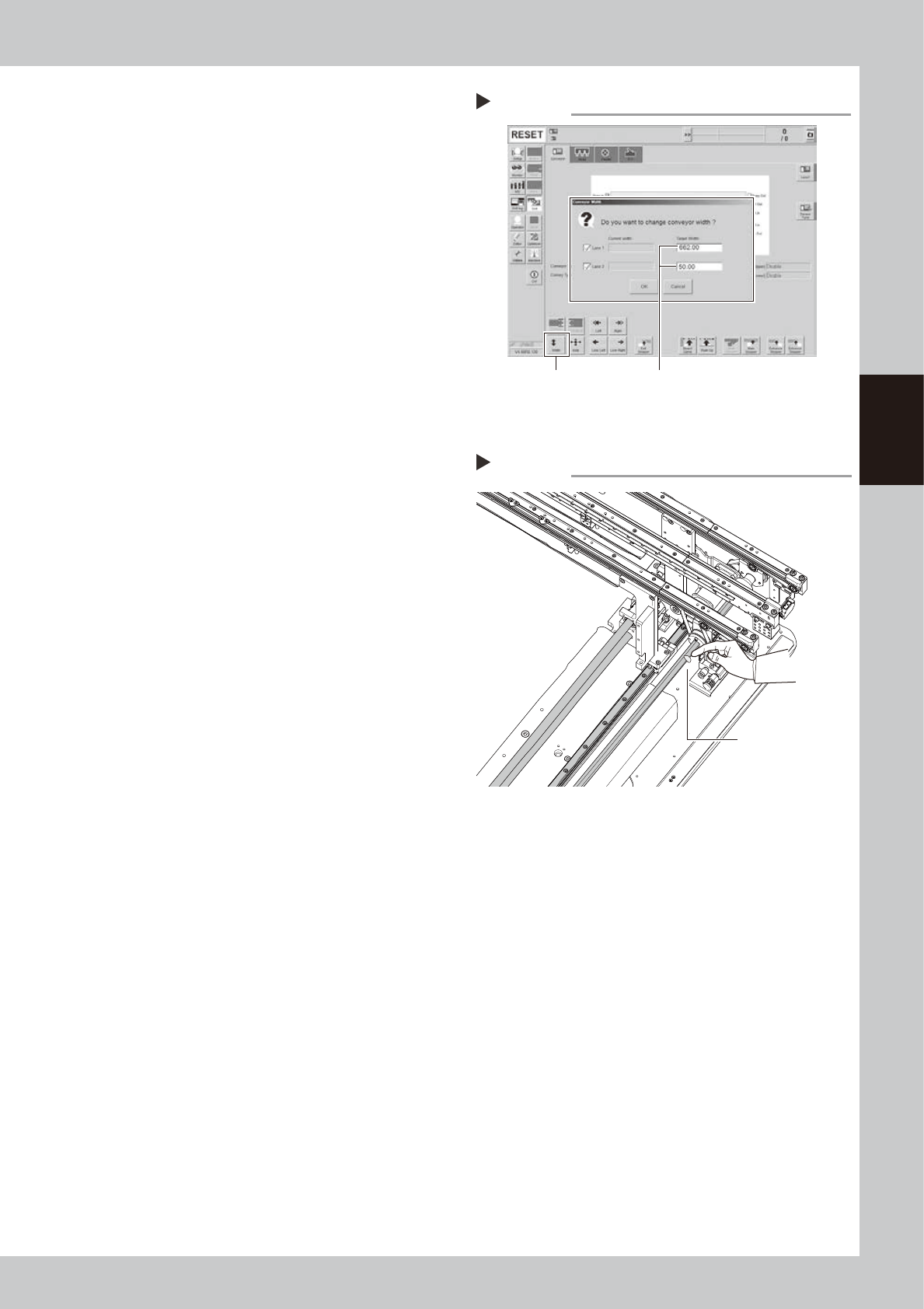
Move the conveyor backward.
e
1. Press the emergency stop button and
then open the machine safety cover.
Attach the carriage if the machine is the
carriage type.
2. Press the [Width] button to display the
"Conveyor Width" screen.
3. Enter "662 mm" in the "Target Width" box
of "Lane 1". Enter "50 mm" in the "Target
Width" box of "Lane 2". Pressing the [OK]
button changes the conveyor width to
the specified width.
e
8
Apply grease to rest of ball screw
and hexagon spline.
1. Press the emergency stop button and
then open the machine safety cover.
2. If the machine is carriage type, detach
carriage to access to the conveyor.
3. Apply the specified grease (NSL) with
finger uniformly over the hexagon spline
shaft surface and ball screw surface and
groove where grease could not be
applied in Step 5.
9
Spread the grease.
1. Close the machine safety cover and
cancel the emergency stop.
2. Change the conveyor width to maximum
and minimum several times referring to
Step 1 and Step 7.
e
0
Wipe away excess grease.
1. Press the emergency stop button and
then open the machine safety cover.
2. If the machine is carriage type, detach
carriage to access to the conveyor.
3. Wipe away excess grease on the edge
of ball screw, guide, and hexagon spline
shaft with lint-free cloth.
Step 7
Moving conveyor backward
[Width] button Enter following values.
Lane 1 : “662 mm”
Lane 2 : “50 mm”
54324-KMK-00
Step 8
Applying grease to W-axis 2
Apply grease to
remaining area.
533A9-KMK-00
3-62
3
Periodic maintenance items
5.4 Cleaning shaft tip
When the shaft tip dirt is found in "3.4 Checking shaft tip" previously described, clean the shaft tip following
the procedure below.
5.4.1 HM head: Cleaning shaft tip
1
Remove nozzles from all heads.
With nozzle station:
1. Open [Unit] - [Head] screen.
2. Select desired head unit from "Table
Select".
3. Press the [Nozzle Change] button.
4. Select "ALL" for Head Number and select
"Store nozzle" for Nozzle type on "Nozzle
Change" screen.
5. Pressing the [OK] button stores nozzles of
all heads to the nozzle station.
n
NOTE
If the nozzle station is not equipped with the machine,
open the machine safety cover and remove nozzles
manually.
2
Move head unit to work position.
Press [Head Pos. Front] or [Head Pos. Rear]
button on "Setup" screen to move head unit
to convenient position for maintenance work.
TIP
When maintaining 2-beam head units, move the front
head unit to rear and move the rear head unit to front
to easily access to the head unit.
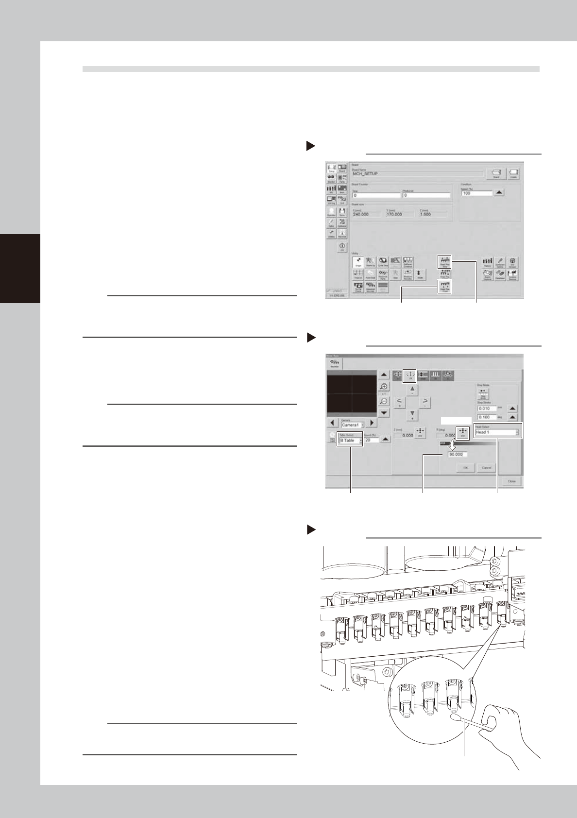
3
Rotate heads 90°.
1. Press [Axis] button on [Unit] - [Conveyor]
screen and select "ZR" tab.
2. Select desired head unit from "Table
Select".
3. Select "Head 1" from "Head Select".
4. Press [PTP] button for R (deg). Enter 90
and press [OK] button. Heads from No. 1
to 5 rotate 90°.
Heads from No. 6 to 10 rotate 90° by
selecting "Head 6" from "Head Select".
and enter 90.
e
5. Press the emergency stop button and
then open the machine safety cover. If
the machine is carriage type, detach
carriage to easily access to the head unit.
4
Clean shaft tip.
Apply ethanol to a cotton swab slightly and
clean shaft tip. Wipe the side of shaft with
twisted cotton swab.
TIP
Lower Z-axis joint block manually if difficult to clean
shaft tip.
Moving head unit
Step 2
[Head Pos. Front] button [Head Pos. Rear] button
54317-KMK-00
Rotating heads
Step 3
Enter 90°. Select head.
[PTP] button
Select table.
54318-KMK-00
Cleaning shaft tip
Step 4
Cotton swab
53399-KMK-00
3-63
3
Periodic maintenance items
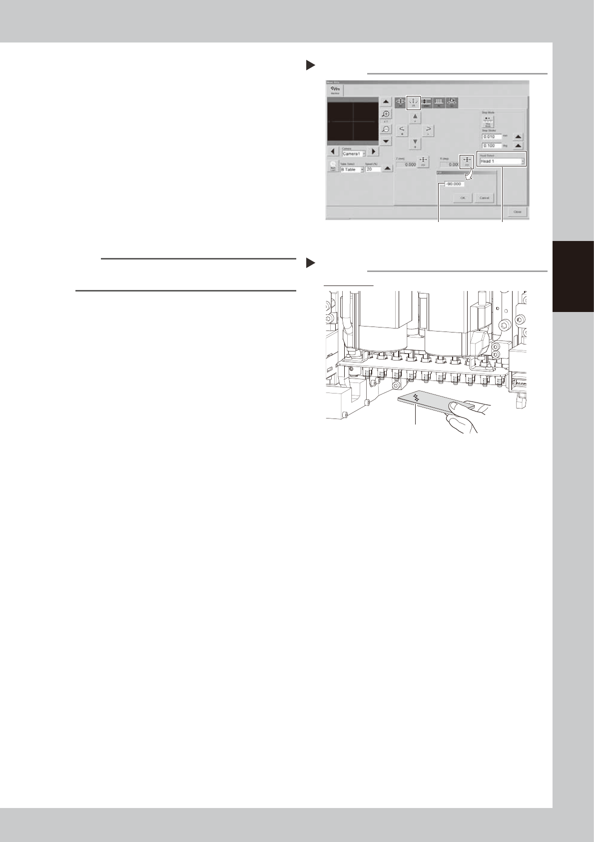
5
Rotate heads -90°.
1. Close the machine safety cover and
release the emergency stop. Attach the
carriage if the machine is the carriage
type.
2. Rotate heads -90° in the same manner as
Step 3.
e
3. Press the emergency stop button and
then open the machine safety cover.
4. If the machine is carriage type, detach
carriage to easily access to the head unit.
6
Clean the back of shaft tip.
Clean the back of shaft tip in the same
manner as Step 4.
TIP
Lower Z-axis joint block manually if difficult to clean
shaft tip.
7
Check that shaft tips are clean.
Check that no dirt remains on shaft tips with
hand mirror.
Checking that shaft tips are clean
Step 7
Check all heads
Hand mirror
533A0-KMK-00
Rotating heads
Step 5
Enter -90°. Select head.
54319-KMK-00