YSM20R_YSM20WR_Mainte_E.pdf - 第175页
6-19 6 How to replace consumable parts r Attach the board clamp plate. Fit the board clamp plate into its original position and tighten the board clamp plate mounting bolts with a hex wrench (3). t Check the belt rotatin…
6-18
6
How to replace consumable parts
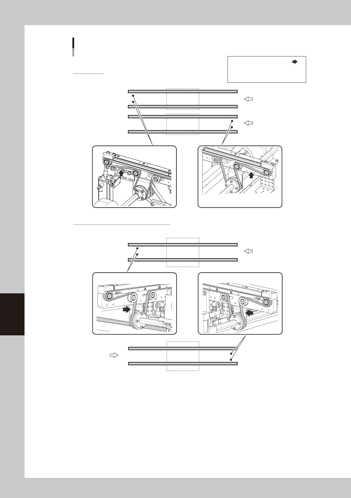
Transfer direction
Transfer direction
Transfer direction
Dual-lane type
Lane 1
Lane 2
STD : 350 - 420 Hz
EXT : 110 - 130 Hz
STD : 350 - 420 Hz
EXT : 110 - 130 Hz
Conveyor belt: Tension measurement locations / Tension standards
YSM20WR
Tension measurement location:
STD: Tension of standard conveyor
EXT: Tension of extended conveyor
Single-lane type (for transferring heavy board)
STD : 274-334 Hz STD : 274-334 Hz
53636-KMK-10
6-19
6
How to replace consumable parts
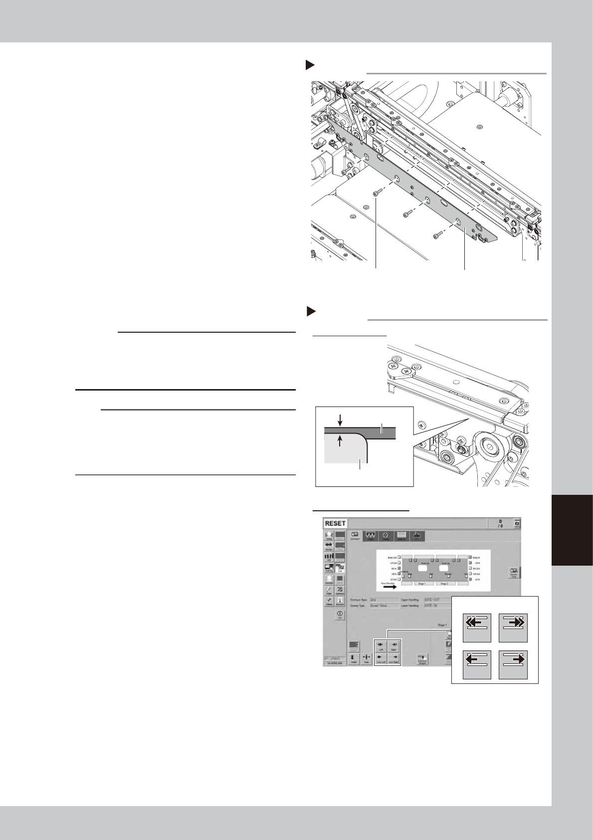
r
Attach the board clamp plate.
Fit the board clamp plate into its original
position and tighten the board clamp plate
mounting bolts with a hex wrench (3).
t
Check the belt rotating condition.
1. Make sure that the board clamp top
surface is approx. 0.5 mm lower than the
belt upper surface.
2. Close the machine safety cover and
cancel the emergency stop. Attach the
carriage if the machine is the carriage
type.
3. On the [Unit]-[Conveyor] screen, press
the [Conveyor In] button or [Conveyor
Out] button to turn on the conveyor
motor and check the belt rotation.
4. If the rotation speed fluctuates or there is
slack in the belt, adjust the position of
the tensioner bolt and then check the
rotation again.
c
CAUTION
When the difference between the belt upper surface
and board clamp top surface is very little, the board
transfer error may occur easily. In this case, contact
your distributor.
n
NOTE
If U-axis is moved manually, an error may occur when
changing the conveyor width after the work.
In this case, see "2.3.1 Checking conveyor sensor
condition and operation" in chapter 3 to perform the
conveyor sensor tuning.
Attaching board clamp plate
Step 14
Board clamp plate
Mounting bolt
53628-KMK-00
Check belt setting and rotation
Step 15
Checking conveyor rotation
Checking belt setting
0.5 mm
Board clamp plate
Belt
Conveyor drive buttons
Left Right
Low Left Low Right
54602-KMK-00
6-20
6
How to replace consumable parts
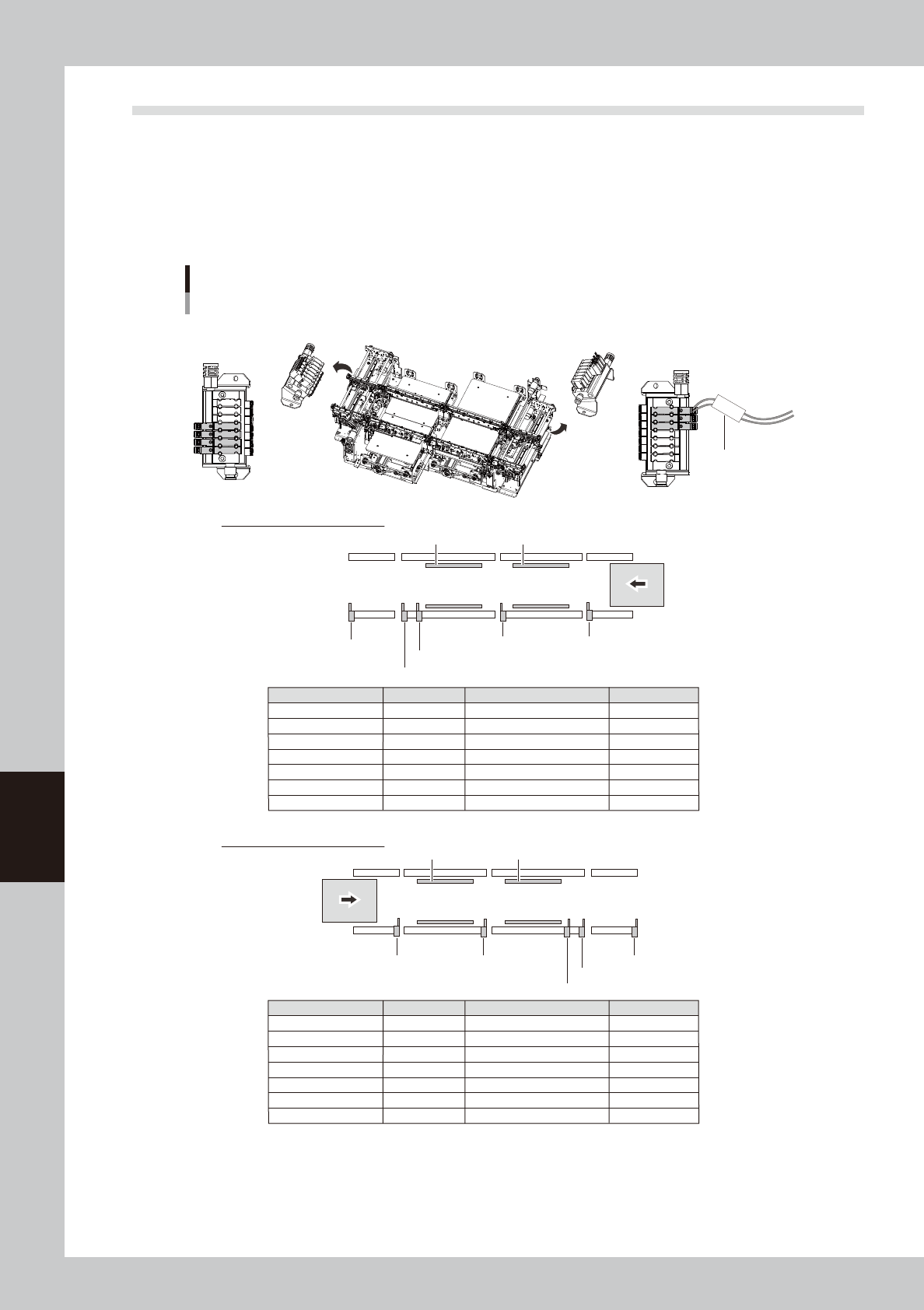
4.2 Replacing conveyor valve
The position of valve that drives conveyor stopper or clamp board and the quantity of valve vary depending on
the machine type and board transfer direction. See the figure below and mark tube on the valve connector wire
to check the valve to be replaced.
n
YSM20R Dual-stage type
The valve assemblies locate on the left and right of conveyor (entrance conveyor/exit conveyor) for dual-stage type.
CV ST1
Positions of conveyor valves
YSM20R Dual-stage type
Sub stopper
Main stopper 2-1
Main stopper 1
Exit stopper
Clamp 1
Clamp 2
Main stopper 2-2
Sub stopper
Main stopper 2-1
Main stopper 1 Exit stopper
Clamp 1Clamp 2
Main stopper 2-2
Transfer direction from right to left
Mark tube name
CV ST1
CV ST3
CV ST6
CV ST7
CV ST8
CLAMP1
CLAMP2
Description
Sub stopper
Main stopper 1
Main stopper 2-1
Main stopper 2-2
Exit stopper
Stage 1 clamp board
Stage 2 clamp board
Remarks
Transfer direction from left to right
Mark tube name
CV ST1
CV ST2
CV ST3
CV ST6
CV ST8
CLAMP1
CLAMP2
Description
Exit stopper
Main stopper 2-2
Main stopper 2-1
Main stopper 1
Sub stopper
Stage 1 clamp board
Stage 2 clamp board
Remarks
Mark tube
Valve assembly
Valve assembly
Stage 1Stage 2
Stage 1Stage 2
Valve position
Right side
Right side
Left side
Left side
Left side
Right side
Left side
Valve position
Right side
Right side
Right side
Left side
Left side
Right side
Left side
53631-KMK-00