YSM20R_YSM20WR_Mainte_E.pdf - 第187页
A-4 Appendix 1.3.2 NEXT INTERF ACE connector When the following three conditions are met, the NEXT INTERF A CE circuit in the machine allo ws the board to be carried out. 1. Machine is read y for carrying in a board ( La…
A-3
Appendix
1.3 Connection between machines
To exchange signals such as board request and operation status with the downstream or upstream machine, the
"NEXT INTERFACE" and "PREVIOUS INTERFACE" connectors located on the rear of the machine are used. The
"NEXT INTERFACE" connector connects to the downstream machine, and the "PREVIOUS INTERFACE"
connector connects to the upstream machine such as a loader.
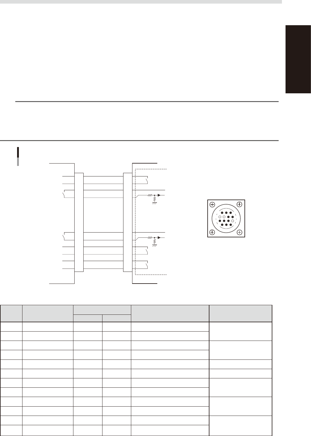
1.3.1 PREVIOUS INTERFACE connector
When the following three conditions are met, the PREVIOUS INTERFACE circuit in the machine allows the next
board to be carried in. (ADVANCED GATE is selected.)
1. Machine is ready for carrying in a board (
Lane 1 BUSY OUT [T0100035] : ON /
(
Lane 2 BUSY OUT [T0100040] : ON
)
2. Board carry-in signal is input from the upstream machine. (
Lane 1
BA IN [N0100416] : ON /
(
Lane 2
BA IN [N0100420] : ON
)
3. Automatic operation signal is input from the upstream machine. (
Lane 1
UR IN [N0100417] : ON /
(
Lane 2
UR IN [N0100421] : ON
)
n
NOTE
• When the automatic operation signal (UR IN) from the loader turns off during transfer of a board, the machine
temporarily stops carrying in the board.
• When the board being carried in is detected by the entrance sensor, the BUSY OUT signal turns off.
• Carrying in the board is finished when both the BUSY OUT and BA IN turn off.
• The addresses of the lane 2 are used for the machines with the dual-lane specifications.
1
2
3
4
5
6
7
8
9
10
11
12
13
14
7
12
4
8
1
14
11
3
BUSY OUT
(LANE 1:T0100035)
(LANE 2:T0100040)
+24V
+24V
LR OUT
(LANE 1:T0100034)
(LANE 2:T0100037)
UR IN
(LANE 1:N0100417)
(LANE 2:N0100421)
BA IN
(LANE 1:N0100416)
(LANE 2:N0100420)
Signal input during
board carry-in
Signal output to
request board carry-out
Signal output during
automatic operation
Signal input during
automatic operation
LE OUT
(LANE 1:T0100036)
(LANE 2:T0100041)
Signal input during
waiting for board
between machines
I/O BOARD
PREVIOUS INTERFACE circuit
This machine PREVIOUS INTERFACEUpstream
PREVIOUS INTERFACE
connector
AMP 206043-1
(14-pin receptacle)
53A04-KMK-00
n
Board transfer signal specifications (PREVIOUS INTERFACE)
Pin No. Signal name
Address
I/O specifications Signal specifications
LANE 1 LANE 2
*1
1 BUSY OUT T0100035 T0100040 Relay contact (zero voltage) output
Signal output during board
carry-in
2 BUSY OUT T0100035 T0100040 Relay contact (zero voltage) output
3 +24V Input common (+24V)
Signal input of board carry-
out request
4 BA IN N0100416 N0100420 Voltage input
5 NC (with dummy pins) (Prevents misinsertion.)
6 to 8 NC
9 +24V Input common (+24V)
Signal input during
automatic operation
10 UR IN N0100417 N0100421 Voltage input
11 LR OUT T0100034 T0100037 Relay contact (zero voltage) output
Signal output during
automatic operation
12 LR OUT T0100034 T0100037 Relay contact (zero voltage) output
13 LE OUT T0100036 T0100041 Relay contact (zero voltage) output
Signal output during
waiting for board between
machines
14 LE OUT T0100036 T0100041 Relay contact (zero voltage) output
*1 Used for dual-lane type machine
A-4
Appendix
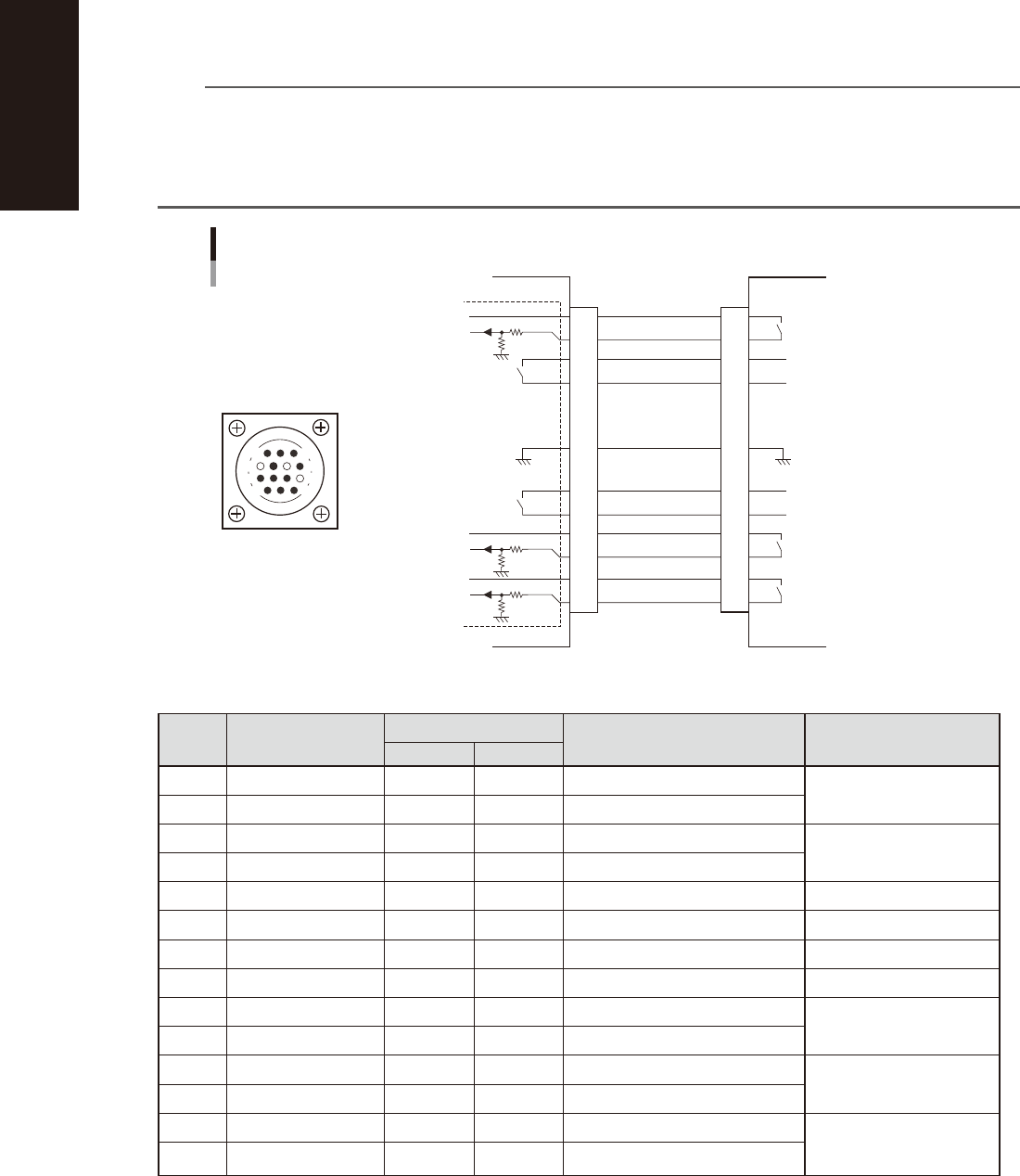
1.3.2 NEXT INTERFACE connector
When the following three conditions are met, the NEXT INTERFACE circuit in the machine allows the board to
be carried out.
1. Machine is ready for carrying in a board (
Lane 1 BA OUT [T0100031] : ON / Lane 2 BA OUT [T0100033] : ON
)
2. Board carry-in signal is input from the upstream machine. (
Lane 1
BUSY IN [N0100410] : ON /
Lane
2 BUSY IN [N0100413] : ON
)
3. Automatic operation signal is input from the upstream machine. (
Lane 1
LR IN [N0100411] : ON /
Lane
2 LR IN [N0100414] : ON
)
n
NOTE
• When the automatic operation signal (LR IN) from the downstream machine turns off during transfer of a board,
the machine stops temporarily carrying out the PC.
• When the board being carried out is detected by the exit sensor, the BA OUT signal turns off.
• Carrying out the board is finished when both the BUSY IN and BA OUT turn off.
• The addresses of the lane 2 are used for the machines with the dual-lane specifications.
1
2
3
4
5
6
7
8
9
10
11
12
13
14
14
11
12
7
4
8
3
1
NEXT INTERFACE circuit
NEXT INTERFACE
connector
This machine NEXT INTERFACE Downstream machine
AMP 206043-1
(14-pin receptacle)
BUSY IN
(LANE 1:N0100410)
(LANE 2:N0100413)
+24V
+24V
UR OUT
(LANE 1:T0100030)
(LANE 2:T0100032)
LR IN
(LANE 1:N0100411)
(LANE 2:N0100414)
+24V
LE IN
(LANE 1:N0100412)
(LANE 2:N0100415)
BA OUT
(LANE 1:T0100031)
(LANE 2:T0100033)
Signal output during board
carry-in
Signal input to request board
carry-out
Signal input during automatic
operation
Signal output during automatic
operation
Signal output during waiting
for board between machines
I/O BOARD
GND GND
53A05-KMK-00
n
Board transfer signal specifications (NEXT INTERFACE)
Pin No. Signal name
Address
I/O specifications Signal specifications
LANE 1 LANE 2
*1
1 +24V Input common (+24V)
Signal input during board
carry-in
2 BUSY IN N0100410 N0100413 Voltage input
3 BA OUT T0100031 T0100033 Relay contact (zero voltage) output
Signal output to request
board carry-out
4 BA OUT T0100031 T0100033 Relay contact (zero voltage) output
5 NC
6 NC (with dummy pins) (Prevents misinsertion.)
7 GND
8 NC
9 UR OUT T0100030 T0100032 Relay contact (zero voltage) output
Signal output during
automatic operation
10 UR OUT T0100030 T0100032 Relay contact (zero voltage) output
11 +24V Input common (+24V)
Signal input during
automatic operation
12 LR IN N0100411 N0100414 Voltage input
13 +24V Input common (+24V)
Signal input during
waiting for board between
machines
14 LE IN N0100412 N0100415 Voltage input
*1 Used for dual-lane type machine
A-5
Appendix
2. Maintenance parts
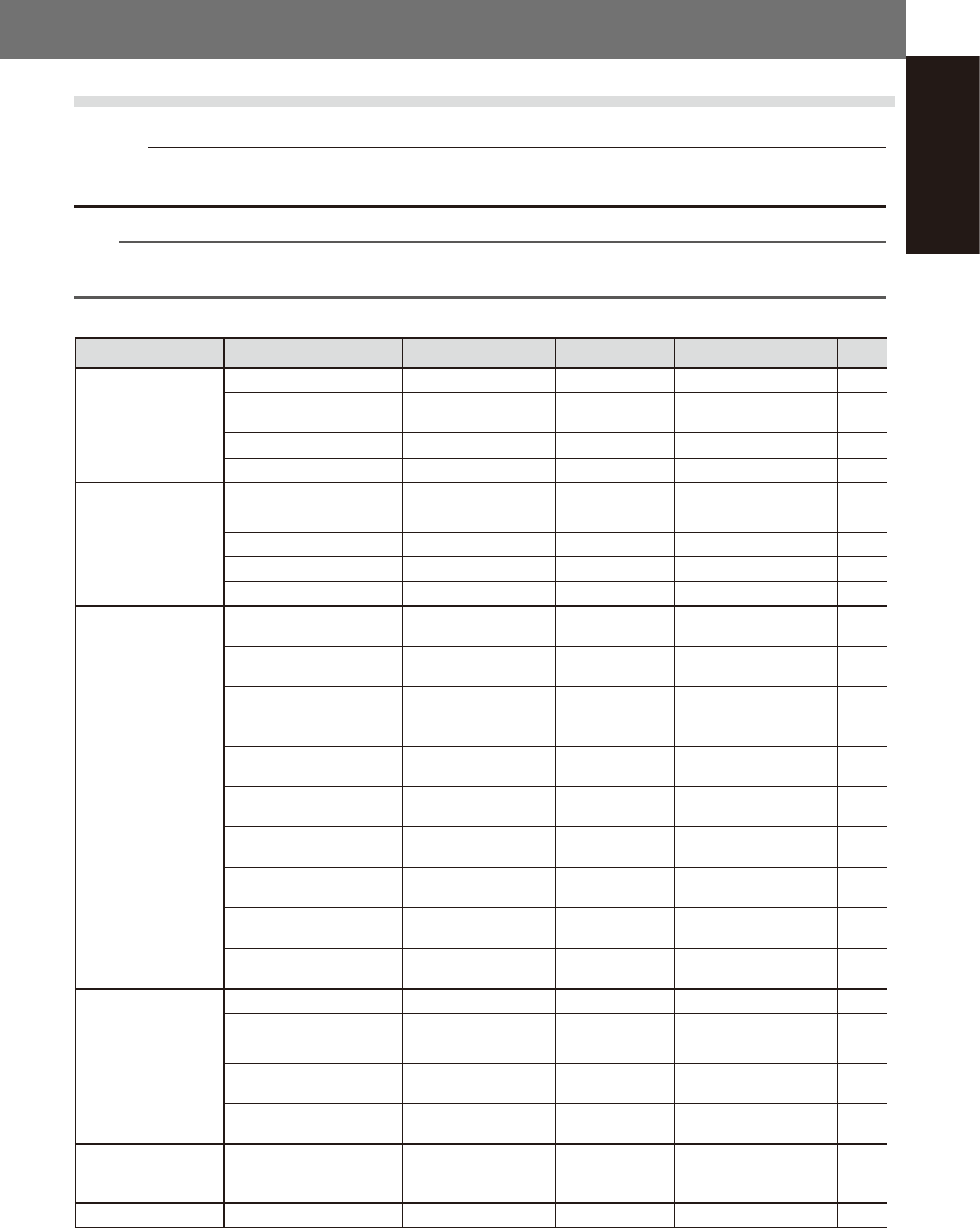
2.1 YSM20R/YSM20WR consumable parts list
c
CAUTION
The parts (Part Nos.) in this manual are at the time of issuing this manual. The Part Nos. may be changed without prior
notice. Make sure to verify the latest Part Nos. before ordering.
n
NOTE
• The consumable part positions and the replacement procedure are described in this manual.
• See "2.1 Consumable parts" in chapter 1 for nozzle consumable parts.
n
Consumable parts list
Position Name Part name Part No. Note Qty
HM head unit Nozzle leaf spring LEAF SPRING KG7-M7137-A0X 20
*3
Leaf spring for strengthening
nozzle holding force
PLATE, SPRING KGS-M714W-03X 20
*3
Ejector filter FILTER KLW-M8527-00X 10
*3
Gasket for filter GASKET KLW-M715B-00X 10
*3
FM head unit Nozzle leaf spring PLATE, SPRING KV7-M8171-00X 10
*3
Nozzle holding roller ROLLER KV7-M81D4-00X 10
*3
Nozzle arm assembly ROLLER LOCK ASSY. KLW-M74D0-00X 5
*3
Ejector filter FILTER KLW-M8527-00X 5
*3
Gasket for filter GASKET KLW-M715B-00X 5
*3
Conveyor belt
YSM20R Dual-stage type
Entrance/Exit
W1/W4 axes
BELT, CONVEYOR KMK-M917H-00X
Length: 605 mm
Width: 6 mm
4
*1
YSM20R Dual-stage type
Stage 1/2
W2/W3 axes
BELT, CONVEYOR KMK-M9110-00X
Length:1175 mm
Width: 6 mm
4
*1
YSM20R Dual-stage type
Entrance/Exit extended
W1/W4 axes
BELT, CONVEYOR KMK-M957H-00X
Length: 975 mm
Width: 6 mm
4
*1
YSM20R Single-lane type
Standard
BELT, CONV.(2916) KMK-M9113-00X
Length: 2916 mm
Width: 7 mm
2
*1
YSM20R Single-lane type
Both side extended
BELT, CONV.(3656) KMK-M9513-00X
Length: 3656 mm
Width: 7 mm
2
*1
YSM20R Single-lane type
One side extended
BELT, CONV.(3286) KMK-M9513-10X
Length: 3286 mm
Width: 7 mm
2
*1
YSM20WR Dual-lane type
Standard
BELT, CONV.(2916) KMK-M9113-00X
Length: 2916 mm
Width: 7 mm
4
*1
YSM20WR Dual-lane type
Both side extended
BELT, CONV.(3656) KMK-M9513-00X
Length: 3656 mm
Width: 7 mm
4
*1
YSM20WR Dual-lane type
One side extended
BELT, CONV.(3286) KMK-M9513-10X
Length: 3286 mm
Width: 7 mm
4
*1
Air/mist filter Filter element FILTER ELEMENT KLF-M8502-50X Air filter (Media) 1
Mist filter element MIST FILTER ELEMENT KLF-M8502-70X Mist filter (Media) 1
Base filter Air intake filter FILTER, FAN KMG-M13NC-00X Filter for cooling Y-axis 4
Air intake filter
(machine rear left)
FILTER, REAR FAN KLW-M13NB-00X
Air intake filter for
machine rear
1
Air intake filter
(control box)
FILTER KLV-M4136-00X
Air intake filter for
control box
1
Ionizer (Option)
Ionizer discharge needle set
(5 pcs)
NEEDLE SPARE SET KJX-M83P1-00X
5 pcs
2 sets are required per
ionizer
2
*2
UPS (Option) UPS battery UPS, BATTERY KGA-M6566-30X 1
*1
Required quantity for 2 conveyor rails of fixed and movable sides /
2
Required quantity per ionizer /
*3
Required quantity per head unit