YSM20R_YSM20WR_Mainte_E.pdf - 第53页
2-2 2 Daily maintenance items 1. Checking the nozzle Solder sticking to the nozzle tip or a clogged nozzle hole can cause component pickup errors and recognition errors. Poor nozzle spring action can also cause pickup an…
2-1
2
Daily maintenance items
Before beginning work
In most cases, maintenance should be performed after powering off the machine.
However, some maintenance tasks are performed under emergency stop conditions powering on the machine.
In such cases, ensure adequate safety and press the emergency stop before beginning the maintenance.
Power on the machine during maintenance when any servo-axis must be operated or machine operation
checked. In this case, also ensure adequate safety before beginning the maintenance.
When operating the machine, make sure the following conditions are met.
n
Operating conditions
1. Supply air pressure is kept at correct pressure.
2. All safety covers are closed.
3. When the machine is equipped with exchange carriages, all exchange carriages are clamped.
4. Nozzles and other units are attached in place.
n
NOTE
The description "Cancel the emergency stop." is in the procedures of this manual. It means "releasing the emergency
stop and pressing the [Ready] button to turn the servo on".
n
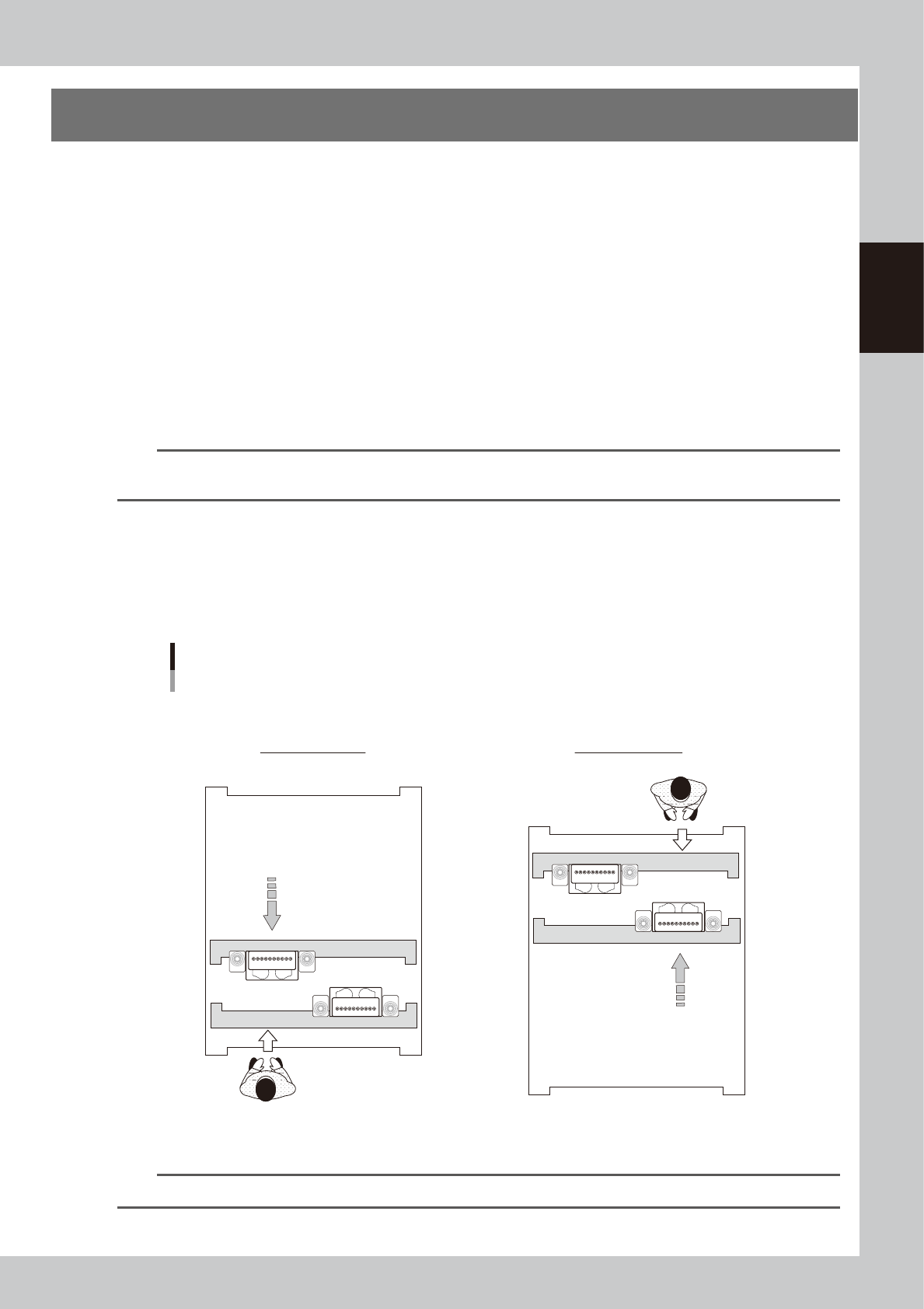
Maintaining head units
When maintaining 2-beam head units, move the front head unit to rear and move the rear head unit to front to easily
access to the head unit.
Head units
2-beam type (Example: front/rear HM heads)
■ Maintaining head units
Machine front
Maintaining rear head
Maintaining front head
Machine front
Move head unit.
Move head unit.
53204-KMK-00
n
NOTE
The [Head Pos. Front] and [Head Pos. Rear] buttons on "Setup" screen are convenient to move head units.
2-2
2
Daily maintenance items
1. Checking the nozzle
Solder sticking to the nozzle tip or a clogged nozzle hole can cause component pickup errors and
recognition errors. Poor nozzle spring action can also cause pickup and mounting errors. To prevent such
problems, inspect each nozzle daily.
1.1 Checking with software
n
How to check for a dirty nozzle (with the [Tip Dirt Check] button)
The term "dirty nozzle" as used here indicates shiny material such as solder adhering to the nozzle tip. This
shiny portion might be mistaken for a component and cause recognition errors. [Tip Dirt Check] is a tool that
judges nozzle contamination status by recognizing nozzle tip in the non-component status with the camera.
n
NOTE
As [Tip Dirt Check] is a function recognizes the reflection
of the light around the nozzle center, applicable nozzles
are those with a small tip, such as 301A, 302A, and 311A.
n
NOTE
Since the nozzle specification may vary depending on
the machine, some machines may require additional
settings. For details about settings, contact YAMAHA
sales representatives.
1
(Without nozzle station) Replace
the nozzle.
1. Press the [Required Nozzles] button on
the "Setup" screen to check the nozzles
to be used for production.
e
2. Press the emergency stop button and
then open the machine safety cover.
3. Attach nozzles to be used for production
to head.
4. Close the machine safety cover and
then cancel the emergency stop.
n
NOTE
Step 1 can be skipped if the machine is equipped with
the nozzle station.
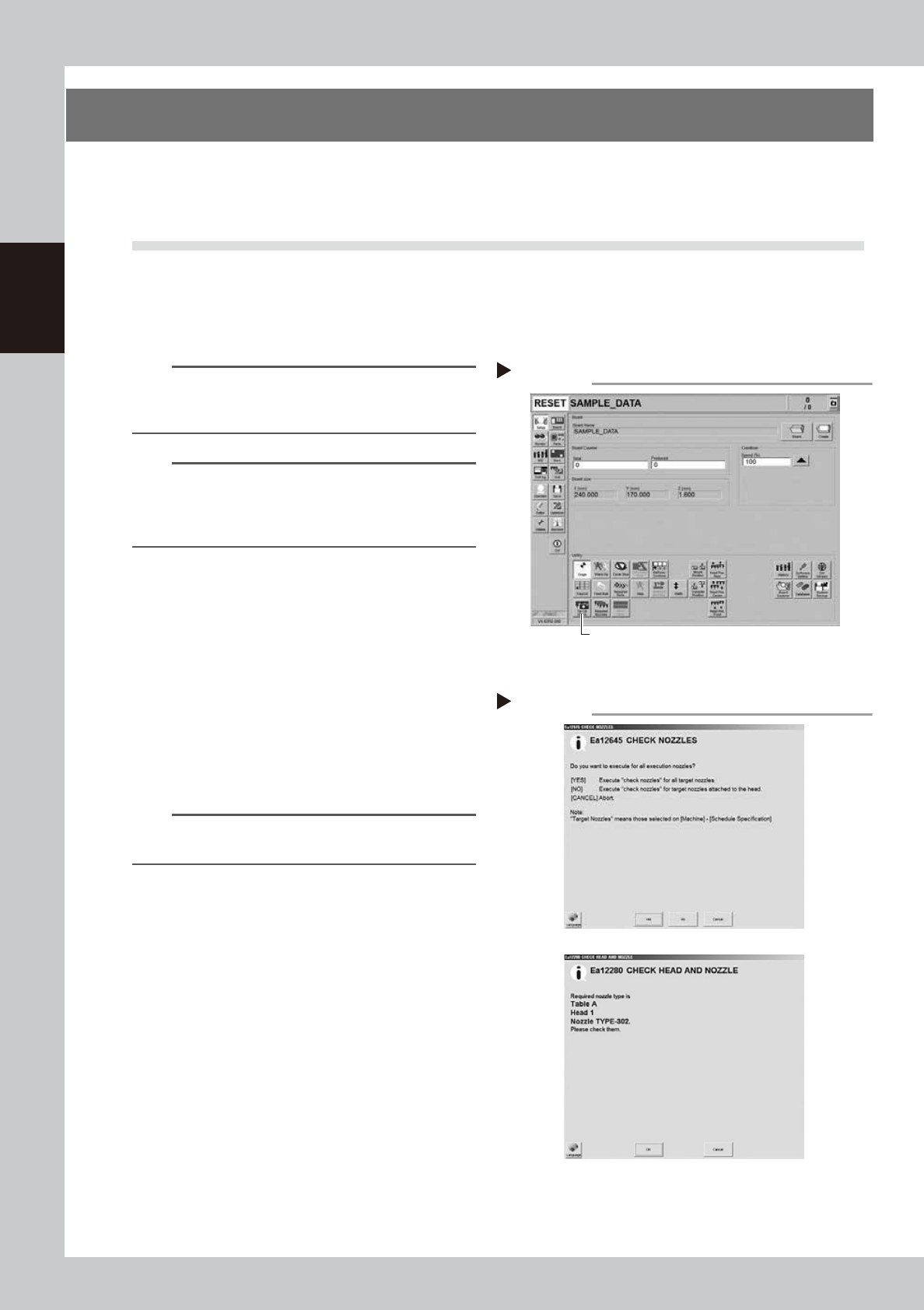
2
Press the [Tip Dirt Check] button
on the "Setup" screen.
3
Select the item to be executed.
After checking the displayed message,
select the desired button.
n
When selected [Yes]
Performs auto nozzle change and checks all relevant
nozzles.
n
When selected [No]
Checks relevant nozzles of all nozzles currently
attached to the head.
4
Check the message.
Check the message. If the result is Not OK,
clean the nozzle referring to "1.2 Nozzle
cleaning" in Chapter 3.
Selecting the item to be executed
Step 3
When [No] was selected
54201-KMK-00
Pressing the [Tip Dirt Check] button
Step 2
[Tip Dirt Check] button
54200-KMK-00
2-3
2
Daily maintenance items
n
How to check for clogged nozzles (on the [Unit]-[Head] tab screen)
The term "clogged nozzle" used here indicates that material such as solder is adhering to the nozzle hole, causing a rise
in negative pressure even if no component is being picked up by the nozzle. This state might cause problems such as
component mounting errors. Check for clogged nozzles with the following procedure, which is described using the Type
302A HM Head as an example.
n
NOTE
The vacuum level when nozzle is open, which is the criterion for clogged nozzle, varies depending on the nozzle types.
See the next page "1.1.1 Vacuum level when nozzle is open" for the vacuum level when nozzle is open other than Type
302A nozzle.
e
1
Attach the nozzles.
n
Without nozzle station
1. Press the emergency stop button and
then open the machine safety cover.
2. Attach Type 302A nozzles to all heads.
n
With nozzle station
1. Press the [Nozzle Change] button and
attach Type 302A nozzles to all heads.
2. Perform "Table Select" and attach nozzles
to both A and B head units.
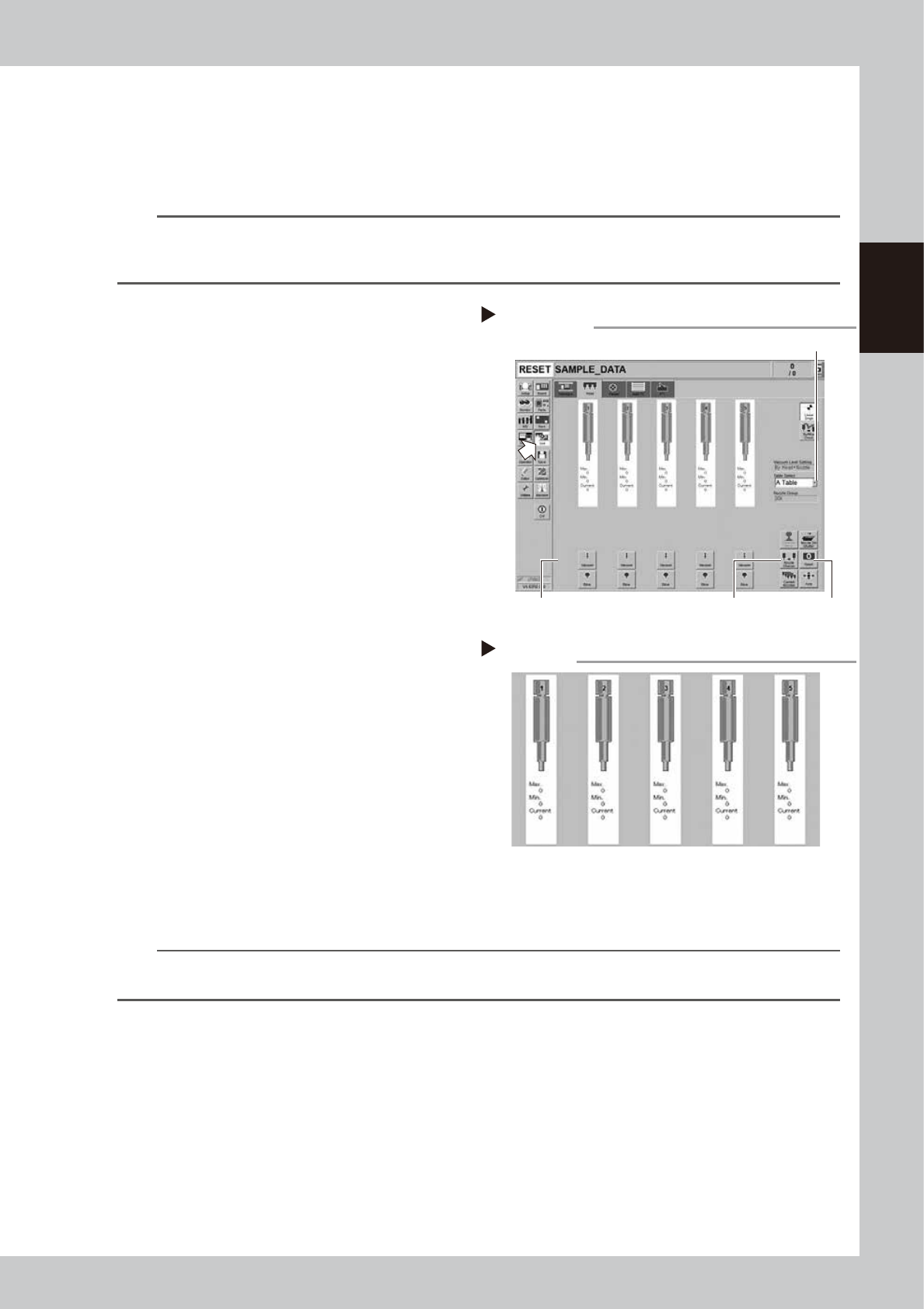
2
Reset the numerical figure.
Open the [Unit] - [Head] tab screen. Then
press the [Reset] button on the lower right of
the screen to reset the pickup level values.
Perform the table selection and reset the
pickup level values of all tables.
3
Generate negative pressure.
On the [Unit] - [Head] tab screen, set the
[Vacuum] buttons for all heads to ON. When
this value starts rising, wait 5 to 10 seconds
and set to OFF. Perform the table selection
and reset the pickup level values of all
tables.
4
Check the vacuum levels.
Change the table sequentially to read all
"Max" values shown in red on the [Head]
screen. If this value is 60 to 110, it is in the
normal range. If higher than 110, the nozzle
hole might be dirty. Clean the nozzle while
referring to "1.2 Nozzle cleaning" in Chapter 3.
n
NOTE
If a correct value cannot be obtained by performing steps 1 to 4 after cleaning the nozzle, the inside of the spline
shaft might be not clean.
Negative pressure check
Step 4
54203-KMK-00
Negative pressure generation
Step 1 to 3
[Nozzle Change] button
[Vacuum] button [Reset] button
[Table selection] button
54202-KMK-00