YSM20R_YSM20WR_Mainte_E.pdf - 第6页
iv Safety instructions 2. Label positions The following warning/caution labels are attached to the Y AMAHA products to ensure safe and correct use. Check that the information on each label is clearly legible and comply w…
iii
Safety instructions
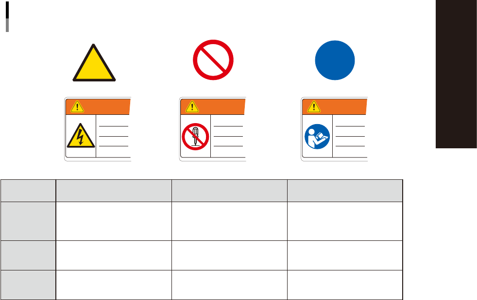
1.1.2 Mark description
The following 3 types of marks are used on warning labels. Each mark has its own meaning and is typically
used with a pictogram to emphasize the message.
Warning mark
Usage examples
Prohibition mark Instruction mark
WARNING WARNINGWARNING
Mark and pictogram
Marks and examples used with pictogram
93002-YSM-00
Definition Shape/Color
Meaning of the above
examples
Warning
Indicates a hazard, how to
avoid the hazard, and potential
consequences of ignoring the
warning.
Yellow triangle with black
border. Pictogram is black on
yellow.
Risk of electrical shock
Prohibition
Indicates a prohibited action to
avoid the potential hazard.
Red circle with slash. Pictogram
is black and located behind
slash.
Do not modify or disassemble
safety cover switch.
Instruction
Indicated an action that must
be taken to avoid the potential
hazard.
Blue circle. Pictogram is white
on blue.
Read the manual to understand
procedure before starting
operation.
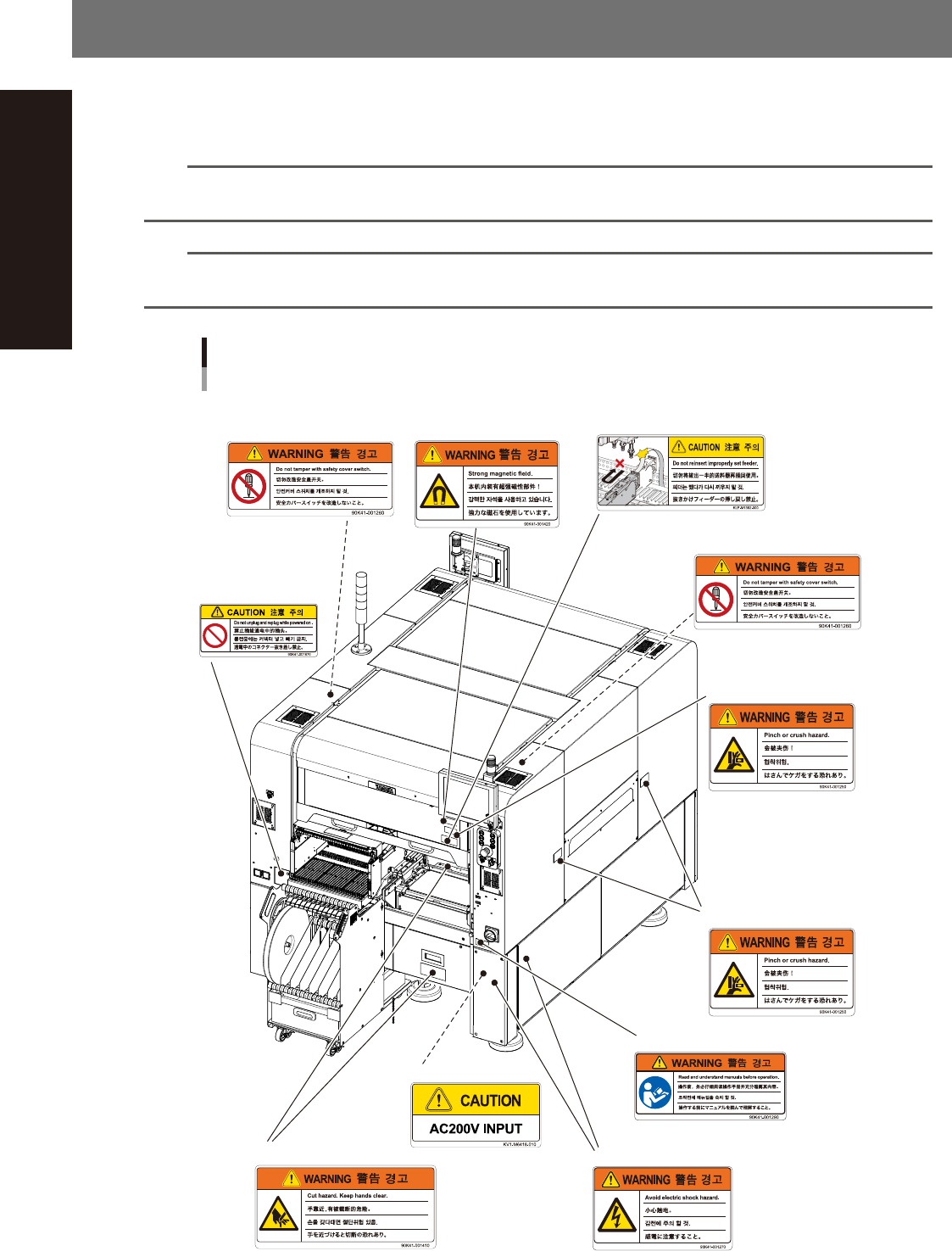
iv
Safety instructions
2. Label positions
The following warning/caution labels are attached to the YAMAHA products to ensure safe and correct use.
Check that the information on each label is clearly legible and comply with the instructions.
For safety precautions other than those on the labels shown in this section, see the instructions in "3. Safety".
n
NOTE
Basically, labels are attached to the positions shown below, although they may differ slightly depending on the
machine model.
n
NOTE
When connecting power to this equipment, refer to "Power connection terminals" described in the appendix of the
maintenance manual or user's manual.
Warning/caution labels
Front
■ Open/close cover inner side
(front and rear sides)
■ Panel
■ Cutter section
■ Open/close cover
(front and rear sides)
■ Open/close cover
(front and rear sides)
■ Conveyor opening
(front and rear sides,
right and left sides)
■ Open/close cover inner side
(front and rear sides)
■ Main switch
■ Feeder setup section
(front and rear sides)
■ Power connecting
93011-KMK-00
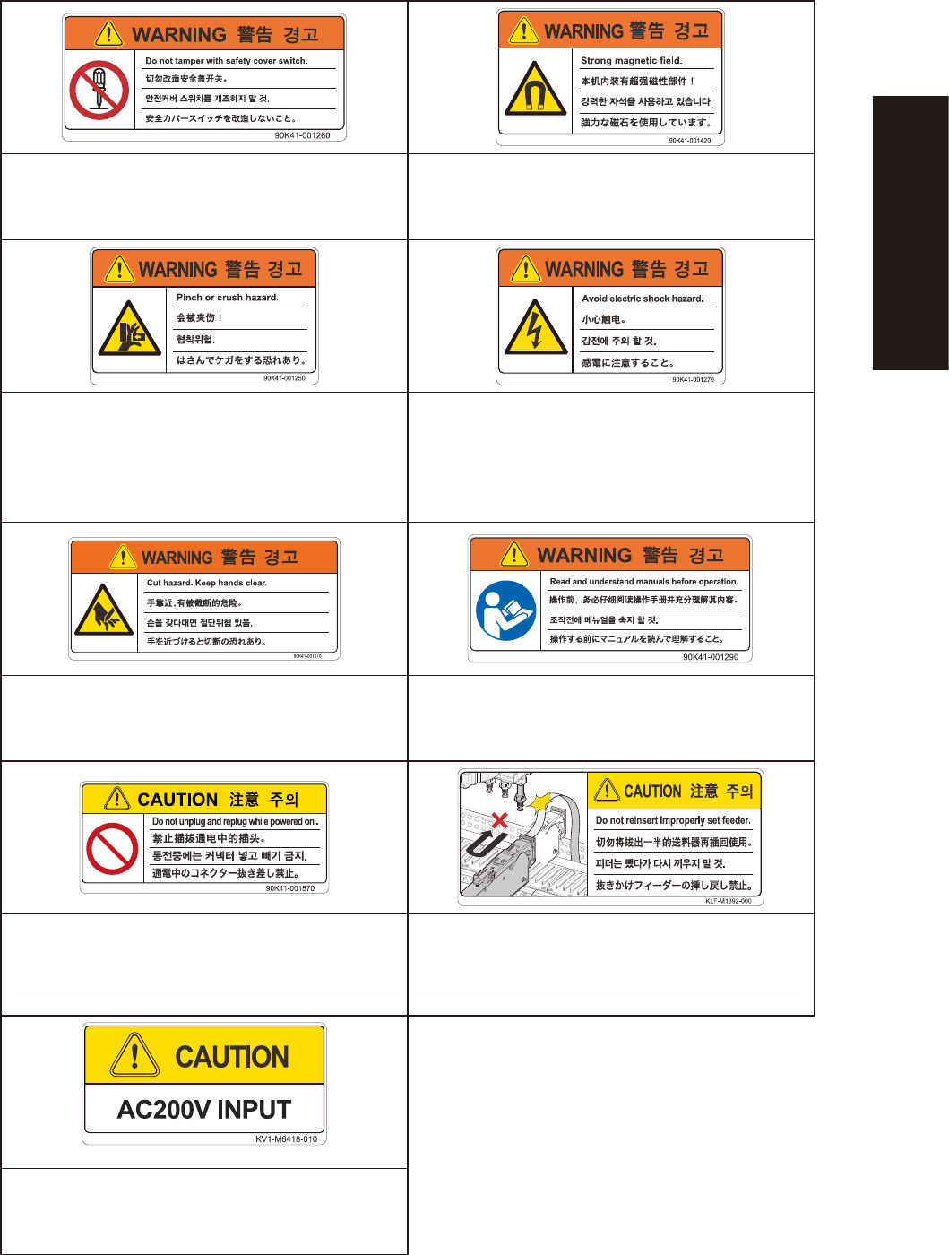
v
Safety instructions
Injury from touching moving parts during machine operation Death, serious injury or equipment malfunction
Do not touch or tamper with safety cover switches and do not
operate machine if any safety cover switches were deactivated.
Observe precautions necessary due to strong magnetic fields.
· Hands or fingers might be caught between moving parts
and covers, causing injury.
· Hands or fingers might be pinched by moving parts,
causing injury.
Electrical shock hazard
Never place hands or fingers in machine during operation
such as when handling tray magazines.
Do not touch power supply inside cover.
Injury from tape cutter Damage to machine or injury to person
Do not put hands into cutter unit while power or air is
supplied.
Before handling the product (equipment) always read manuals
and make sure you fully understand the contents.
Machine damage
The carrier tape could make contact with the head,
possibly causing machine damage.
Do not insert or remove any connector while power is on.
When a feeder is extracted from its loaded position, be sure
that the feeder has been completely extracted before pressing
it back into its loaded position.
Machine damage or malfunction
Connect power only at the specified voltage.