YSM20R_YSM20WR_Mainte_E.pdf - 第79页
3-18 3 Periodic maintenance items 7 Perform a w arm-up. 1. Remove the square cloth. 2. Close the machine safety cover and cancel the emergency stop. Detach the carriage if the machine is carriage type. e 3. Open the Warm…
3-17
3
Periodic maintenance items
2.2 Y-axis
This section explains the Y-axis inspection, cleaning, and lubricating procedures. For details regarding
lubrication points and the lubrication condition, see "Chapter 5 Lubrication points".
2.2.1 Cleaning/lubricating Y-axis guide and cleaning linear scale
1
Prepare for work.
1. Take off all accessories susceptible to the
magnetic fields, such as a wristwatch
and/or magnetic ID card.
e
2. Press the emergency stop button and
then open the machine safety cover.
3. Detach the carriage if the machine is the
carriage type.
4. Place a square cloth on the push-up
plate.
2
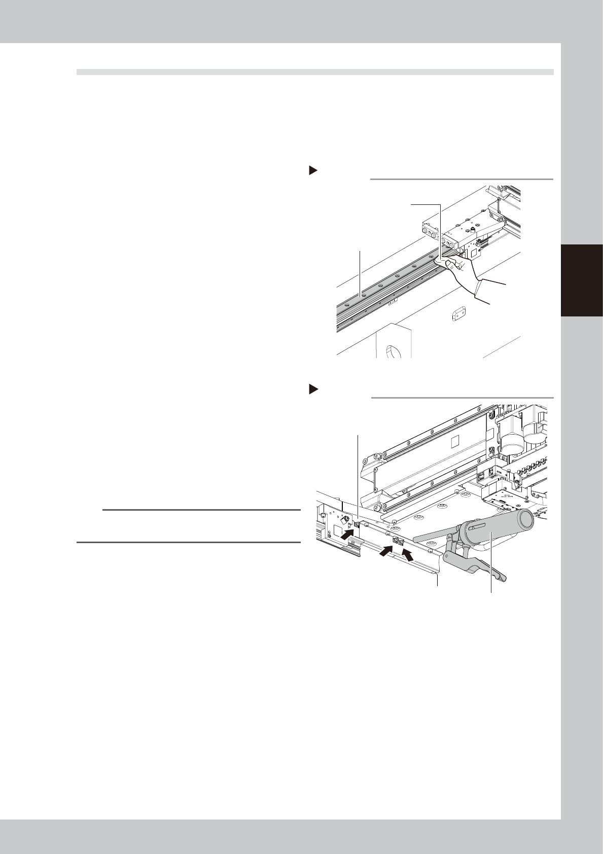
Clean the guide.
1. Move the head unit to one end manually.
2. Use lint-free cloth to wipe the entire
guide.
3. Move the head unit forward manually.
Wipe the positions where cleaning could
not be performed in 2.
3
Inject the grease.
Use a grease gun (bent type nozzle) to inject
the specified grease (NSL) from the grease
nipples (6 locations/table) for the Y-axis
guide.
4
Spread the grease.
Move the head unit back and forth several
times manually to spread the grease.
n
NOTE
The grease injected through the nipple oozes to the
guide when moving the axis.
5
Wipe off the excess grease.
Wipe off the excess grease from both ends
of the guide.
6
Apply the grease again.
Repeat Steps 3 to 5 twice again.
After that, visually check that the grease is
applied to the entire guide.
Cleaning the guide
Step 2
Cloth
Guide
53326-KMK-00
Injecting the grease
Step 3
Grease gun (Standard type)
Grease nipple
53327-KMK-00

3-18
3
Periodic maintenance items
7
Perform a warm-up.
1. Remove the square cloth.
2. Close the machine safety cover and
cancel the emergency stop. Detach the
carriage if the machine is carriage type.
e
3. Open the Warm-up screen, and perform
the warm-up operation for approximately
8 minutes.
4. After stopping warming up, press the
emergency stop button and then open
the machine safety cover.
5. Wipe the grease accumulated on the
guide end surface.
c
CAUTION
Repeat Step 7 until grease accumulations no longer
occur. Beginning production with grease accumulations
present could cause the grease to spatter.
8
Clean the linear scale.
Use dry and lint-free cloth to dry-wipe the
linear scale. If significant soiling exists, apply
ethanol to cloth slightly and wipe it in one
direction. Then dry-wipe the area.
c
CAUTION
Do not dry-wipe the linear scale strongly.
Cleaning the linear scale
Step 8
Cloth
Linear scale
Wipe in one direction.
53328-KMK-00
3-19
3
Periodic maintenance items
2.3 Conveyor
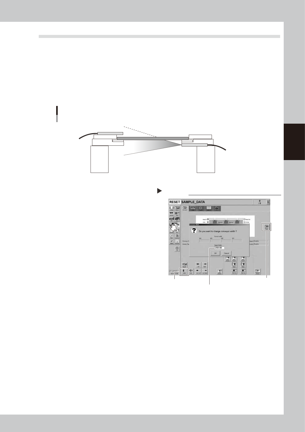
2.3.1 Checking conveyor sensor condition and operation
This machine uses a transmission type fiber sensor as the conveyor sensor.
As the conveyor width changes, the distance between the light emitting and light receiving sensors also
changes. Accordingly, the light receiving status of the sensor may change.
Therefore, a conveyor sensor tuning function is provided on this machine that stores the sensor light receiving
status after the conveyor rail width has been changed and automatically rewrites the sensor threshold value.
By changing the conveyor rail width periodically, you can check that the conveyor sensors and conveyor sensor
tuning operate correctly.
Checking the conveyor sensor condition and operation
Light emitting
Light receiving
53329-KMK-00
1
Make the preparations for work.
Check that there is no board on the
conveyor and that there is no push-up pin in
the conveyor movement range.
2
Open [Unit] - [Conveyor] screen.
3
Press the [Width] button to change
the conveyor width.
The "Conveyor Width" screen appears. Enter
a conveyor width and press the [OK] button.
The conveyor width is changed to the
specified width.
4
Check that no error occurs.
When no error message appears after the
conveyor width has been changed, the
conveyor sensors operate correctly. No
further check is needed.
If an error is displayed, perform the conveyor
tuning following the steps from 5.
5
Perform conveyor sensor tuning.
Press the [Sensor Tune] button on the right of
the [Unit] - [Conveyor] screen.
6
Check the sensor status.
Change the conveyor width again and
check that no error message appears.
7
Check the portion around the
sensor.
If the error message still appears, the light
receiving status around the sensor may be
poor, the sensor (amplifier) may malfunction,
or the fiber may break. First, remove
contaminant or dust from the sensor, change
the conveyor width again, and check that
no error message appears.
Checking the conveyor sensor
Step 2-5
[Sensor Tune] button
Enter desired conveyor width.
[Width] button
54301-KMK-00