YSM20R_YSM20WR_Mainte_E.pdf - 第88页
3-27 3 Periodic maintenance items 3.6 FM head: Cleaning/lubricating around Z-axis ball screw When using the FM head, it is normally necessary to clean and lubricate the ball screw , spline shaft, and guide once every 3 m…
3-26
3
Periodic maintenance items
3.5.3 HM head: Applying grease to spline shaft (when required)
n
NOTE
Basically, it is not necessary to apply grease to spline shaft (Z-axis) of HM head unit. However, if touching the shaft
surface or solvent sprayed on it, the grease is removed and rust may appear. Slightly apply specified grease (NSL) for
anti-rust as needed.
e
1
Move the head unit.
1. Press the emergency stop button and
then open the machine safety cover.
2. Move the head unit to easily access to
the head unit.
3. Move the head unit forward.
2
Clean the spline shaft.
Clean the spline shaft with lint-free cloth or
cotton swab.
3
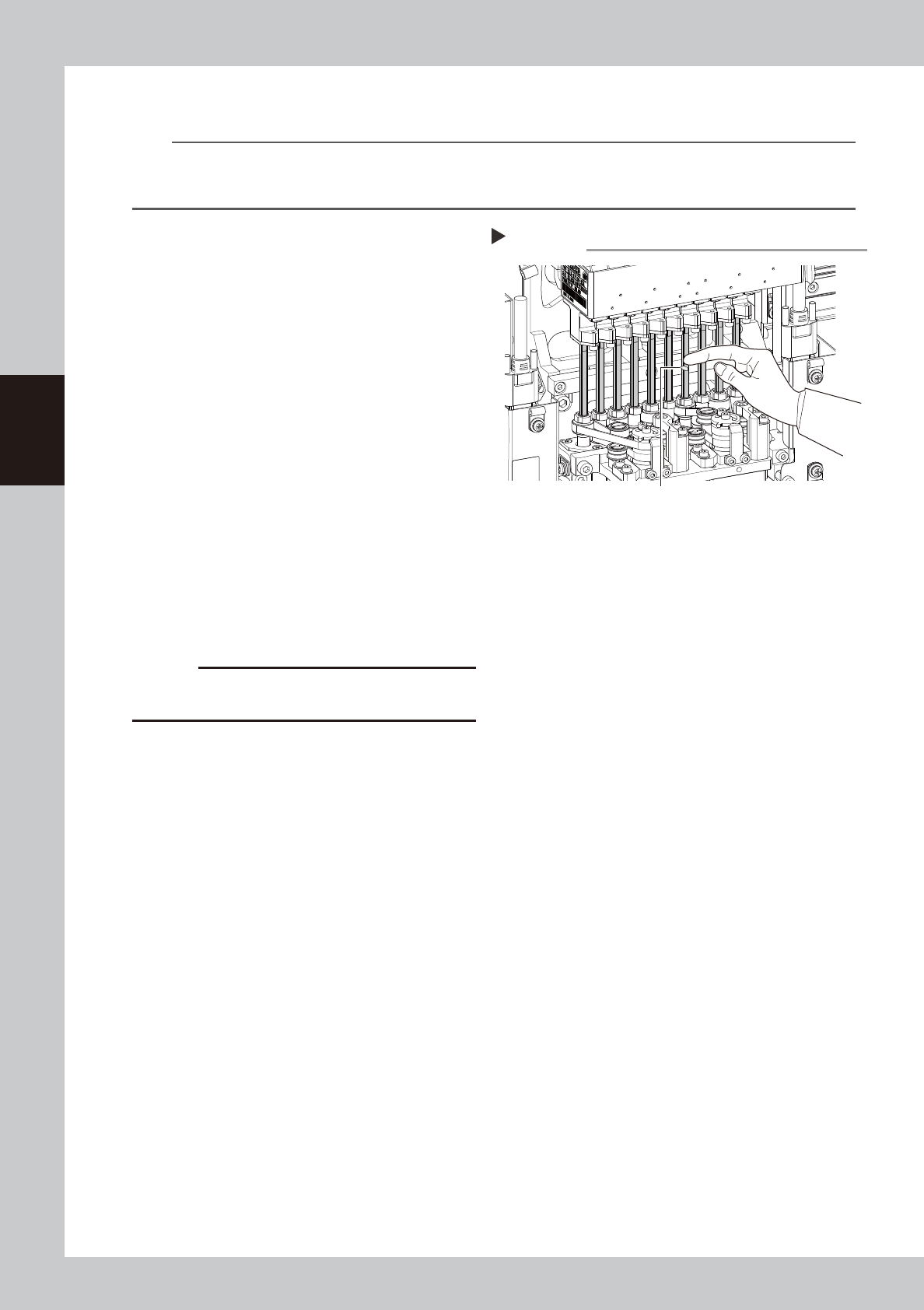
Apply grease to the spline shaft.
Apply and spread thinly specified grease
(NSL) with finger uniformly over the shaft
surface.
4
Wipe off the excess grease.
1. Move up/down the spline shaft several
times manually.
2. Wipe off excess grease on top and
bottom of the spline shaft with lint-free
cloth or cotton swab.
c
CAUTION
Make sure not to wipe off grease on spline shaft surface
completely.
Applying grease to spline shaft
Step 3
Grease (Apply uniformly.)
53335-KMK-00
3-27
3
Periodic maintenance items
3.6 FM head: Cleaning/lubricating around Z-axis ball screw
When using the FM head, it is normally necessary to clean and lubricate the ball screw, spline shaft, and guide
once every 3 months. Follow the steps below to perform the cleaning and lubrication work.
1
Move the head unit.
1. Take off all accessories susceptible to the
magnetic fields, such as a wristwatch
and magnetic ID card.
e
2. Press the emergency stop button and
then open the machine safety cover. If
the machine is carriage type, detach
carriage to easily access to the head unit.
3. Move the head unit to a convenient
position for maintenance work.
4. Place a square cloth under head unit.
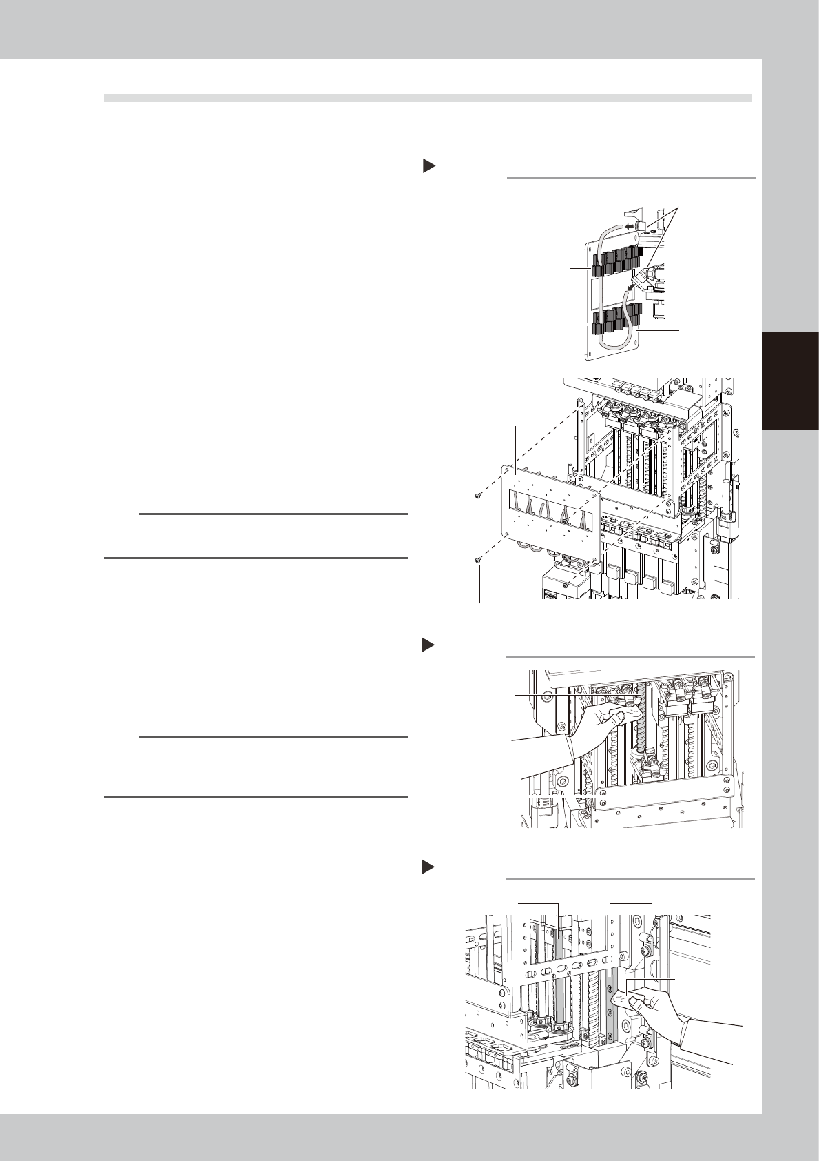
2
Remove the air hose and the front
cover.
1. Remove screws on front cover with hex
wrench (3) holding the cover to avoid
falling.
2. Disconnect the air hose from the top and
bottom joints.
n
NOTE
Remove the air hose while it is attached on the front
cover.
3
Clean the ball screw.
Use a lint-free cloth to wipe off the dust and
dirt on the ball screw.
1. Lower the head and clean the upper
part of the ball screw as shown in the
figure on the right.
2. Raise the head and clean the lower part
of the ball screw.
n
NOTE
Carefully wipe the ball screw until its grooves during
cleaning work. Additionally, check that there is no dust
after cleaning.
4
Clean the spline shaft and guide.
In the same manner as the ball screw, wipe
off contaminants from the spline shaft and
guide with a lint-free cloth while moving the
shaft up and down.
5
Apply the grease to the guide.
Uniformly apply the specified grease (AFF)
with finger. For portions where hand is
difficult to enter, such as the head at the
center, apply the grease using a cotton
swab.
Removing the front cover
Step 2
Rear side of front cover
Air hose
Tube holder
Cover clamp bolt
Joint
Front cover
Front cover
53336-KMK-00
Cleaning the ball screw
Step 3
Cloth
Ball screw
53337-KMK-00
Cleaning the spline shaft and guide
Step 4
Cleaning cloth
Spline shaft
Guide
53338-KMK-00
3-28
3
Periodic maintenance items
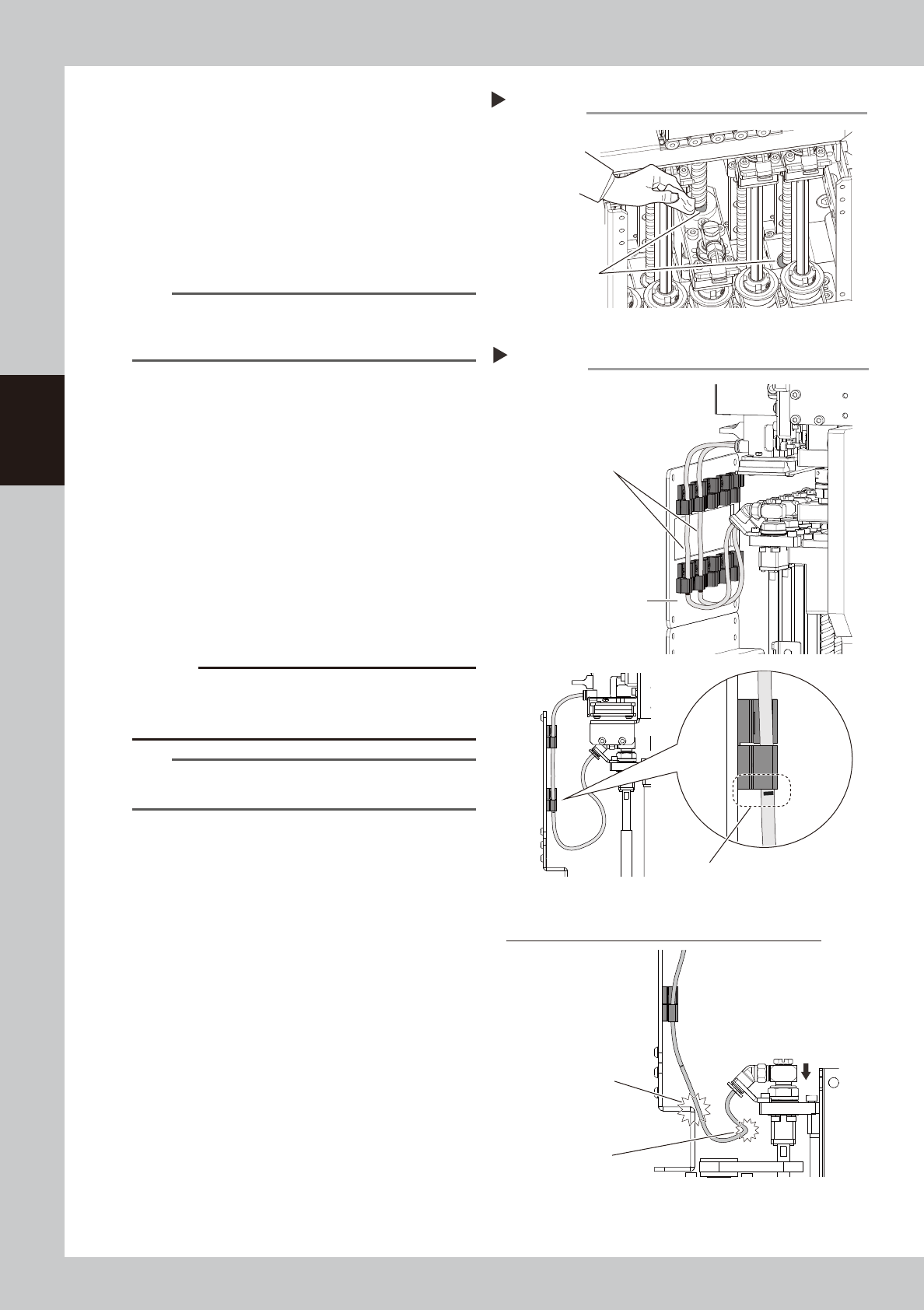
6
Apply the grease to the ball screw.
Uniformly apply the specified grease (NSL)
to the ball screw with finger. For portions
where hand is difficult to enter, such as the
head at the center, apply the grease using
a cotton swab.
7
Apply the grease to the spline shaft.
Uniformly apply the specified grease (LRL) to
the spline shaft with finger.
n
NOTE
This grease application work uses three kinds of grease.
Perform the work while carefully checking that incorrect
grease is not applied.
8
Wipe off the excess grease.
Move the head up and down several times
to wipe off the excess grease of the grease
accumulation portion.
9
Return the head to original state.
1. Attach the air hoses.
2. Attach the front cover.
3. Remove the square cloth.
0
Check the air hose position.
Check that the air hoses are not crossing
and the air hose marking position is aligning
with the bottom of the tube holder.
c
CAUTION
If the air hose position is incorrect, the air hoses are
pulled or bent when the head is lowered. This may
damage the air hoses or parts
.
TIP
The air hose marking position is 80
mm from the lower
end of the hose.
Wiping off the excess grease
Step 8
Grease accumulation
53339-KMK-00
Air hose position
Step 10
Do not cross air hoses.
Make sure that air hose marking position
is aligning with bottom of tube holder.
Front cover
Incorrect attachment of air hoses (when head is lowered)
Air hose is damaged
by hitting.
Bending of air hose
53340-KMK-00