YSM20R_YSM20WR_Mainte_E.pdf - 第90页
3-29 3 Periodic maintenance items 3.7 PU-axis T he PU (push-up) axis is designed to prevent flexing or warping of the board during clamping and is important because it prevents depressing of the board during component mo…
3-28
3
Periodic maintenance items
6
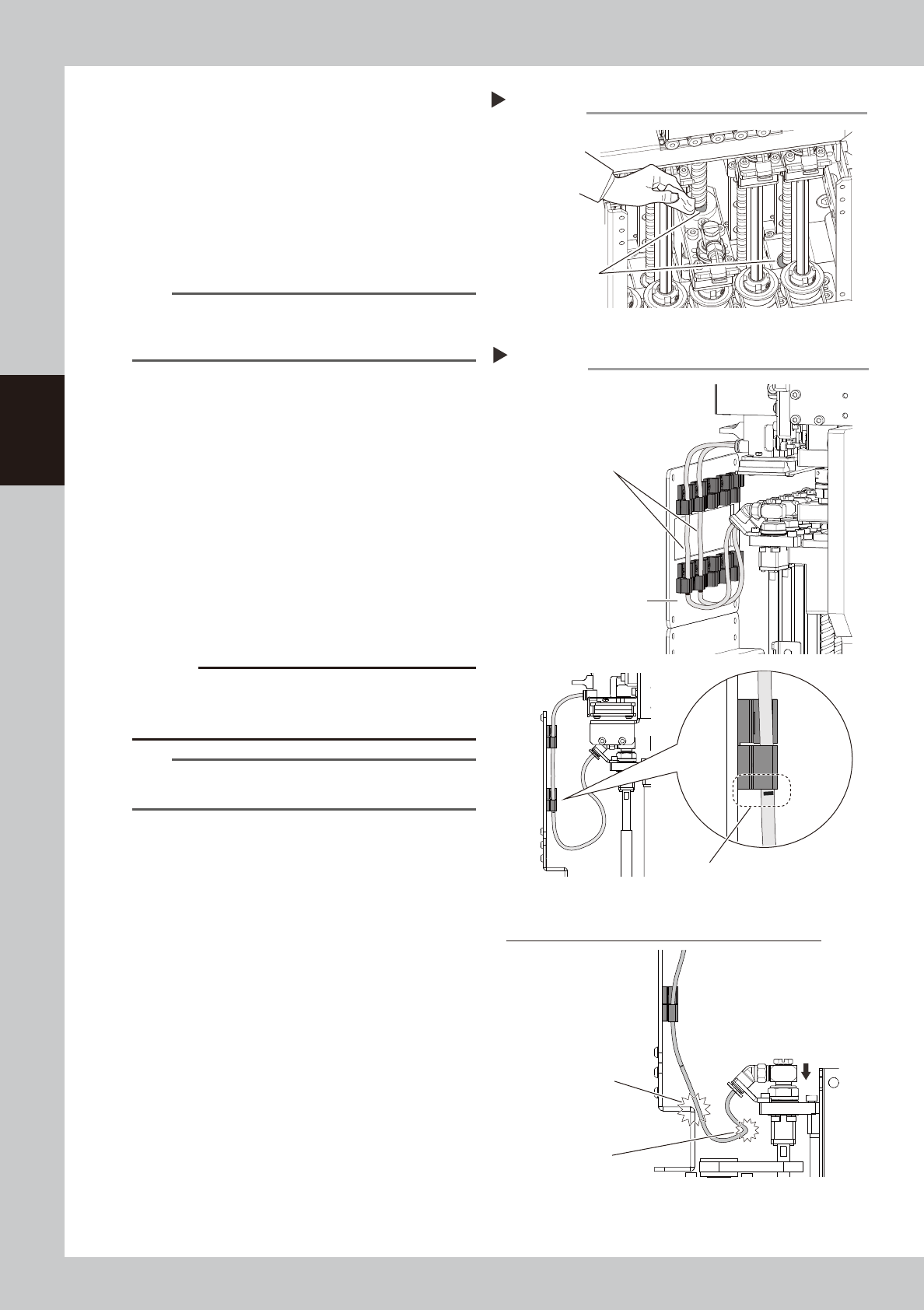
Apply the grease to the ball screw.
Uniformly apply the specified grease (NSL)
to the ball screw with finger. For portions
where hand is difficult to enter, such as the
head at the center, apply the grease using
a cotton swab.
7
Apply the grease to the spline shaft.
Uniformly apply the specified grease (LRL) to
the spline shaft with finger.
n
NOTE
This grease application work uses three kinds of grease.
Perform the work while carefully checking that incorrect
grease is not applied.
8
Wipe off the excess grease.
Move the head up and down several times
to wipe off the excess grease of the grease
accumulation portion.
9
Return the head to original state.
1. Attach the air hoses.
2. Attach the front cover.
3. Remove the square cloth.
0
Check the air hose position.
Check that the air hoses are not crossing
and the air hose marking position is aligning
with the bottom of the tube holder.
c
CAUTION
If the air hose position is incorrect, the air hoses are
pulled or bent when the head is lowered. This may
damage the air hoses or parts
.
TIP
The air hose marking position is 80
mm from the lower
end of the hose.
Wiping off the excess grease
Step 8
Grease accumulation
53339-KMK-00
Air hose position
Step 10
Do not cross air hoses.
Make sure that air hose marking position
is aligning with bottom of tube holder.
Front cover
Incorrect attachment of air hoses (when head is lowered)
Air hose is damaged
by hitting.
Bending of air hose
53340-KMK-00
3-29
3
Periodic maintenance items
3.7 PU-axis
The PU (push-up) axis is designed to prevent flexing or warping of the board during clamping and is important
because it prevents depressing of the board during component mounting.
The PU axis also prevents deviations in the component mounting accuracy due to the board depressing during
component mounting, so it is important to regularly clean and inspect the PU axis to ensure it operates
correctly.
c
CAUTION
If trouble occurs with the PU-axis, contact YAMAHA sales representatives. The disassembly and cleaning of the
machine made by the customer is beyond the coverage of the warrantee.
3.7.1 Cleaning and lubricating PU-axis ball screw
1
Prepare for work.
Take off all accessories susceptible to the
magnetic fields, such as a wristwatch and
magnetic ID card.
2
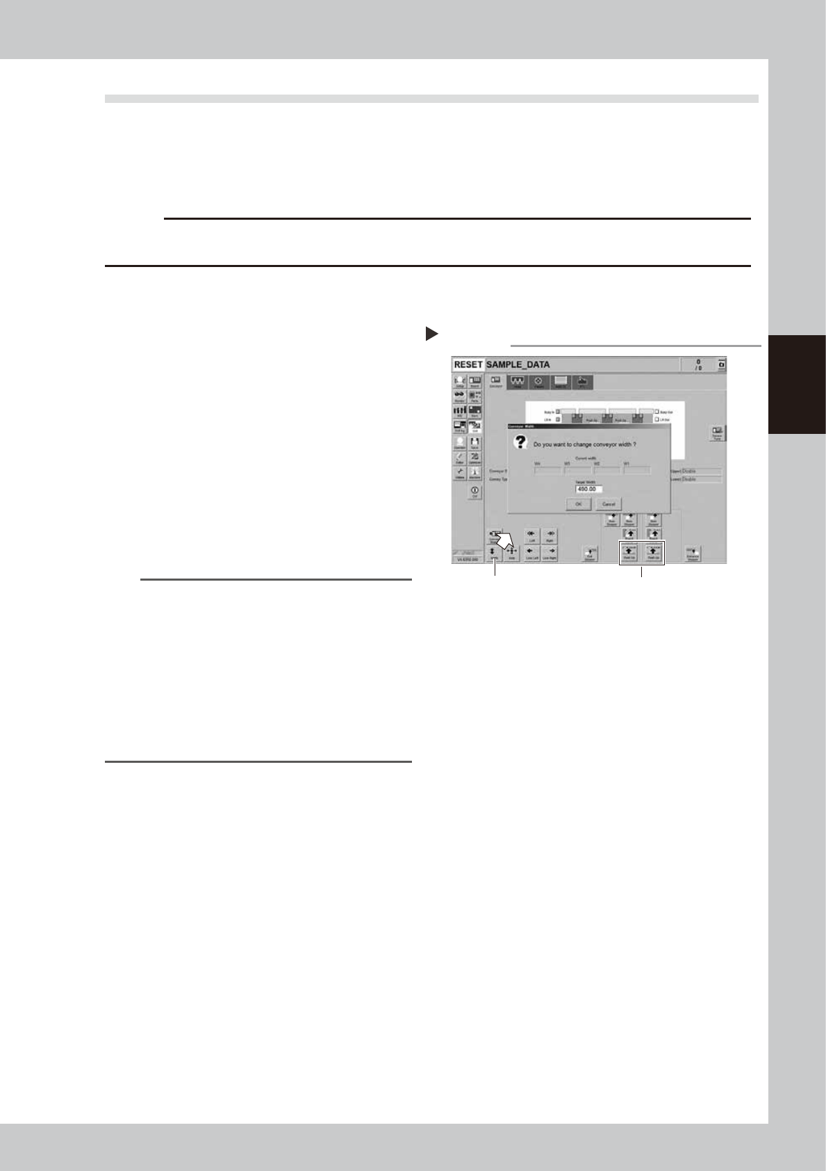
Change the conveyor width to
maximum width.
1. Press the [Width] button on the [Unit]
- [Conveyor] screen to display the
"Conveyor Width" screen.
2. Enter the maximum width in the "Target
Width" box and press the [OK] button.
The conveyor width is changed to the
specified width.
n
NOTE
The conveyor maximum width varies depending on
machine type as below.
YSM20R Dual-stage type : 490 mm
YSM20R Single-lane type : 490 mm
YSM20WR Single-lane type : 742 mm
Regarding YSM20WR Dingle-lane type, enter the
conveyor maximum width of lane 1 or lane 2 according
to the lane to be lubricated.
"Maximum width of one
lane"
YSM20WR Dual-lane type: 662 mm
3
Raise the push-up unit.
1. Press the [Push-up] button on the stage
to perform grease up to display the
“Conveyor Push-up” screen.
2. Enter “0.1 mm” in “Thickness” box and
press the [OK] button. The push-up unit is
raised.
Changing the conveyor width
Step 2,3
Step 3Step 2
54302-KMK-00
3-30
3
Periodic maintenance items
e
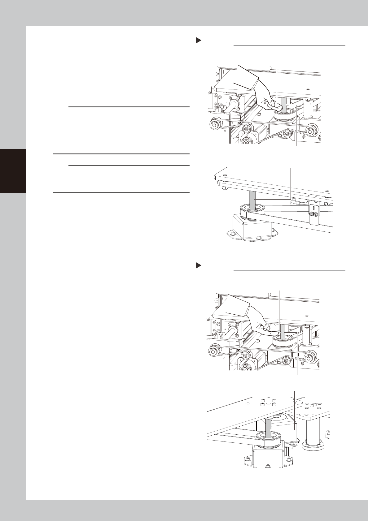
4
Remove the old grease.
1. Press the emergency stop button and
then open the machine safety cover.
2. Detach the carriage if the machine is the
carriage type, .
3. Wipe off the old grease on ball screws
with lint-free cloth.
n
NOTE
The number of PU-axis ball screws depending on
machine type as below.
YSM20R Dual-stage type : 2 places per stage
YSM20R Single-lane type : 2 places
YSM20WR Single-lane type : 3 places
YSM20WR Dual-lane type : 2 places per lane
n
NOTE
Carefully wipe the ball screw until its grooves during
cleaning work. Additionally, check that there is no dust
after cleaning.
5
Apply the new grease by hand.
Apply as much as 2 cm of new grease to
finger and rub it evenly into the ball screw
grooves.
6
Spread the grease.
e
1. Press the emergency stop button and
then open the machine safety cover.
Attach the carriage if the machine is the
carriage type.
2. The push-up unit moves down by pressing
the [Push up] button.
3. Move up and down the push-up unit
several times to spread the grease. After
spreading the grease, put the push-up
unit in its up state.
e
7
Wipe away excess grease by hand.
1. Press the emergency stop button and
then open the machine safety cover.
Detach the carriage if the machine is the
carriage type.
2. Remove excess grease by hand.
8
(YSM20WR Dual-lane)Apply grease
to the other side of lane.
Clean the other side of lane and apply
grease with Steps 2 to 7.
Applying the grease
Step 5
Ball screw (2 places per lane)
Example: YSM20R Dual-stage
Grease
Example: YSM20WR Dual-lane
Ball screw (2 places per stage)
54342-KMK-10
Cleaning the ball screw
Step 4
Cloth
Ball screw (2 places per lane)
Ball screw (2 places per stage)
Example: YSM20R Dual-stage
Example: YSM20WR Dual-lane
53341-KMK-10