YSM20R_YSM20WR_Mainte_E.pdf - 第91页
3-30 3 Periodic maintenance items e 4 Remo ve the old grease. 1. Press the emergency stop button and then open the machine safety cover . 2. Detach the carriage if the machine is the carriage type, . 3. Wipe of f the old…
3-29
3
Periodic maintenance items
3.7 PU-axis
The PU (push-up) axis is designed to prevent flexing or warping of the board during clamping and is important
because it prevents depressing of the board during component mounting.
The PU axis also prevents deviations in the component mounting accuracy due to the board depressing during
component mounting, so it is important to regularly clean and inspect the PU axis to ensure it operates
correctly.
c
CAUTION
If trouble occurs with the PU-axis, contact YAMAHA sales representatives. The disassembly and cleaning of the
machine made by the customer is beyond the coverage of the warrantee.
3.7.1 Cleaning and lubricating PU-axis ball screw
1
Prepare for work.
Take off all accessories susceptible to the
magnetic fields, such as a wristwatch and
magnetic ID card.
2
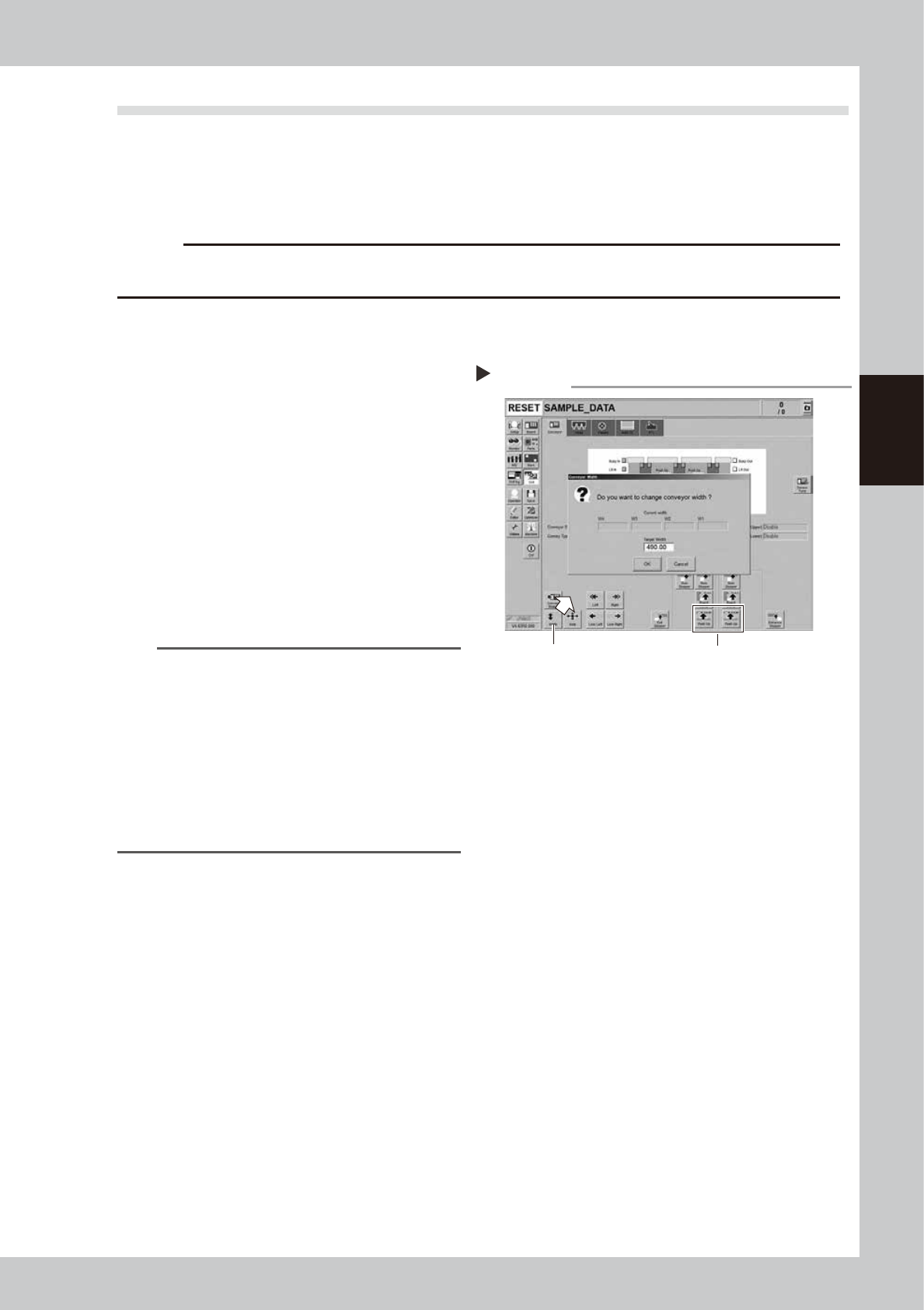
Change the conveyor width to
maximum width.
1. Press the [Width] button on the [Unit]
- [Conveyor] screen to display the
"Conveyor Width" screen.
2. Enter the maximum width in the "Target
Width" box and press the [OK] button.
The conveyor width is changed to the
specified width.
n
NOTE
The conveyor maximum width varies depending on
machine type as below.
YSM20R Dual-stage type : 490 mm
YSM20R Single-lane type : 490 mm
YSM20WR Single-lane type : 742 mm
Regarding YSM20WR Dingle-lane type, enter the
conveyor maximum width of lane 1 or lane 2 according
to the lane to be lubricated.
"Maximum width of one
lane"
YSM20WR Dual-lane type: 662 mm
3
Raise the push-up unit.
1. Press the [Push-up] button on the stage
to perform grease up to display the
“Conveyor Push-up” screen.
2. Enter “0.1 mm” in “Thickness” box and
press the [OK] button. The push-up unit is
raised.
Changing the conveyor width
Step 2,3
Step 3Step 2
54302-KMK-00
3-30
3
Periodic maintenance items
e
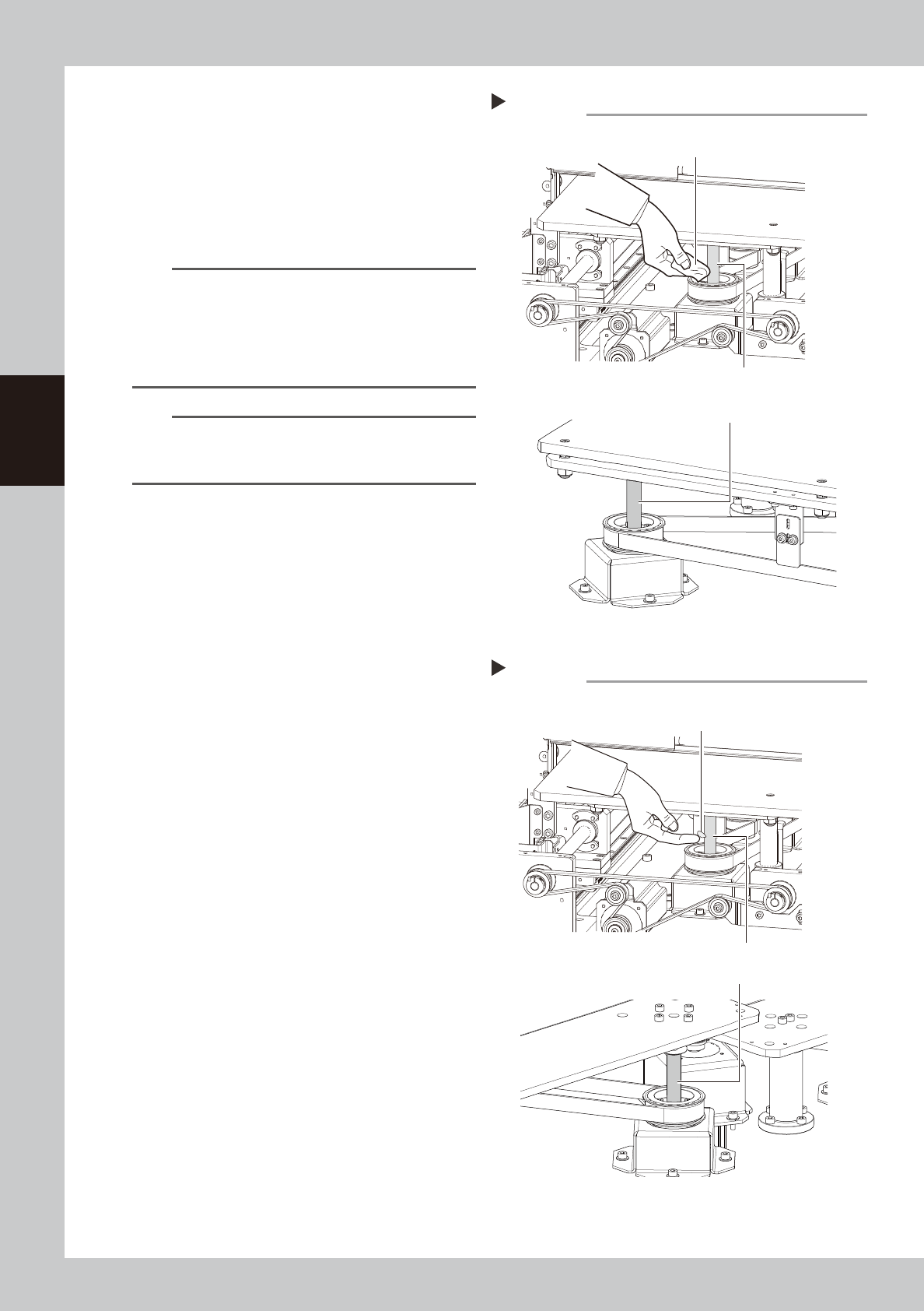
4
Remove the old grease.
1. Press the emergency stop button and
then open the machine safety cover.
2. Detach the carriage if the machine is the
carriage type, .
3. Wipe off the old grease on ball screws
with lint-free cloth.
n
NOTE
The number of PU-axis ball screws depending on
machine type as below.
YSM20R Dual-stage type : 2 places per stage
YSM20R Single-lane type : 2 places
YSM20WR Single-lane type : 3 places
YSM20WR Dual-lane type : 2 places per lane
n
NOTE
Carefully wipe the ball screw until its grooves during
cleaning work. Additionally, check that there is no dust
after cleaning.
5
Apply the new grease by hand.
Apply as much as 2 cm of new grease to
finger and rub it evenly into the ball screw
grooves.
6
Spread the grease.
e
1. Press the emergency stop button and
then open the machine safety cover.
Attach the carriage if the machine is the
carriage type.
2. The push-up unit moves down by pressing
the [Push up] button.
3. Move up and down the push-up unit
several times to spread the grease. After
spreading the grease, put the push-up
unit in its up state.
e
7
Wipe away excess grease by hand.
1. Press the emergency stop button and
then open the machine safety cover.
Detach the carriage if the machine is the
carriage type.
2. Remove excess grease by hand.
8
(YSM20WR Dual-lane)Apply grease
to the other side of lane.
Clean the other side of lane and apply
grease with Steps 2 to 7.
Applying the grease
Step 5
Ball screw (2 places per lane)
Example: YSM20R Dual-stage
Grease
Example: YSM20WR Dual-lane
Ball screw (2 places per stage)
54342-KMK-10
Cleaning the ball screw
Step 4
Cloth
Ball screw (2 places per lane)
Ball screw (2 places per stage)
Example: YSM20R Dual-stage
Example: YSM20WR Dual-lane
53341-KMK-10
3-31
3
Periodic maintenance items
3.8 Base
This machine is equipped with 2 each of air intake fans on machine front and rear (4 in total) for cooling Y-axis.
If failing to clean the filter, the temperature inside of the machine may rise due to filter clogging. Clean the
filters periodically to prevent lowering of the machine function or shortening of the service life.
Note that power off the machine when cleaning as the filter is cleaned after detaching the fan unit.
3.8.1 Cleaning filter for Y-axis cooling fan
1
Power off the machine.
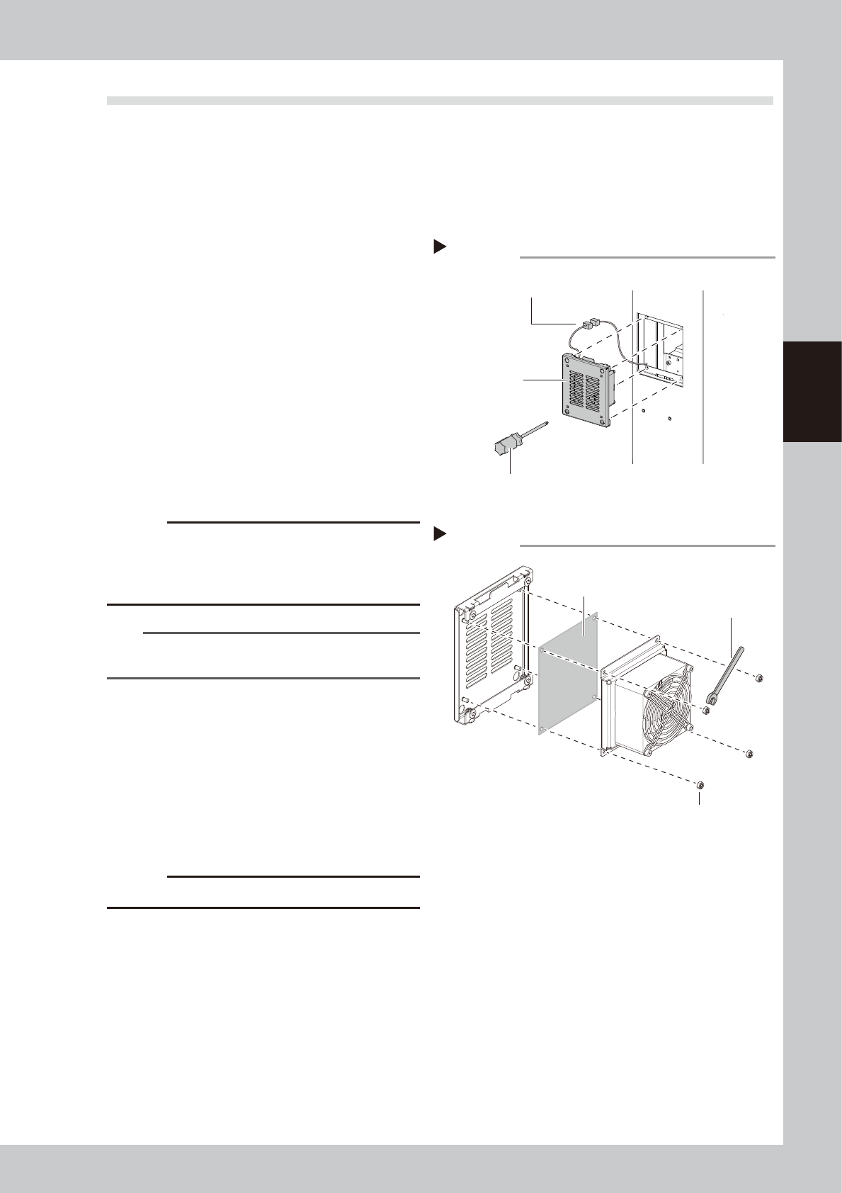
2
Detach the fan unit.
1. Loosen 4 mounting screws with a Phillips
screwdriver to detach the fan unit. It is
not necessary to remove the screws.
2. Disconnect the fan wiring connectors.
3
Pull out the filter.
Remove the fan mounting nuts with a
wrench (7).
4
Clean the filters.
Suck both surfaces of the filter with a
vacuum cleaner or vacuum assembly to
remove dust.
c
CAUTION
If the filters are used while they are damp, the dust
combines with moisture and causes clogging. Since it is
enough to clean the filters with a vacuum cleaner, do
not wash the filters with water.
n
NOTE
If dust cannot be removed or the filter has worn out,
replace the filter with new one.
5
Return the filter to the original
position.
Return the filter to the fan unit.
6
Return the fan unit to the original
position.
1. Reconnect the fan wiring connectors.
2. Return the fan unit to the original
position.
c
CAUTION
Make sure not to catch wires.
Detaching fan unit
Step 2
Fan unit
Phillips screwdriver
Fan wiring connectors
54343-KMK-00
Detaching filter
Step 3
Filter
Wrench (7)
Fan mounting nut
53344-KMK-00