00197498-03_UM_SiplaceCA-Serie_EN.pdf - 第104页
2 Operational Safety User Manual SIPLACE CA- Series 2.10 Disabling the Compressed Air Supply and Discharging the Pre ssure From software version SC.708.0 Edition 12/2014 EN -DR AFT 104 2 Fig. 2.10 - 2 Electrical and pneu…
User Manual SIPLACE CA-Series 2 Operational Safety
From software version SC.708.0 Edition 12/2014 EN -DRAFT 2.10 Disabling the Compressed Air Supply and Discharging the Pressure
103
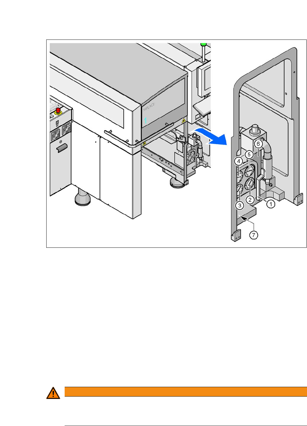
Fig. 2.10 - 1 Compressed air unit on the machine
(1) Shutoff valve
(2) Manometer for the machine component supply pressure
Target pressure: 0.48 ± 0.025 MPa, 4.8 ± 0.25 bar (display range 0 - 0.6 MPa, 0 - 6 bar)
(3) Manometer for gantry distributor supply pressure
Target pressure: 0.46 ± 0.01 MPa, 4.6 ± 0.1 bar (display range 0 - 0.6 MPa, 0 - 6 bar)
(4) Manometer for the bulk case feeder modules supply pressure
Target pressure: 0.25 ± 0.05 MPa, 2.5 ± 0.5 bar (display range: 0 - 0.6 MPa, 0 - 6 bar)
(5) Manometer for inlet pressure
Target pressure: 0.5 - 1.0 MPa, 5 - 10 bar (display range: 0 - 1.0 MPa, 0 - 10 bar)
(6) Compressed air filter
(7) Hexagon socket-head screw for fixing the pneumatic unit
2
WARNING
Risk of injuries!
Risk of injuries from pressurized compressed air lines.
NEVER detach compressed air lines while they are still pressurized.
2 Operational Safety User Manual SIPLACE CA-Series
2.10 Disabling the Compressed Air Supply and Discharging the Pressure From software version SC.708.0 Edition 12/2014 EN -DRAFT
104
2
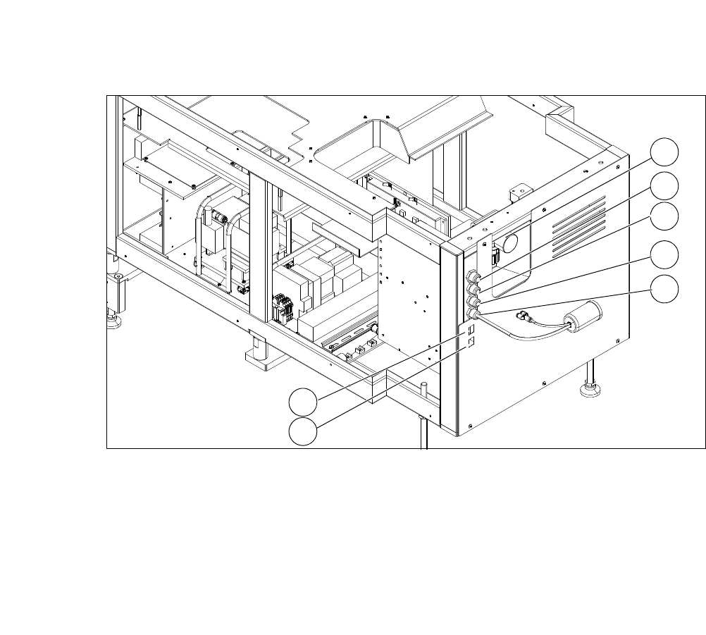
Fig. 2.10 - 2 Electrical and pneumatic connection on the SWS
2
(1) Manometer for compressed air supply (2) Voltage supply
(3) Communication with SIPLACE machine (4) CAN bus
(5) Compressed air connection (modified
adapter dummy connector [03011592-01])
(6) LAN1
(7) LAN2
2
1
3
4
5
6
7
User Manual SIPLACE CA-Series 2 Operational Safety
From software version SC.708.0 Edition 12/2014 EN -DRAFT 2.11 Energy State After Switching off Main Switch
105
2.11 Energy State After Switching off Main Switch
2
2.11.1 Main Switch on Placement Machines
2
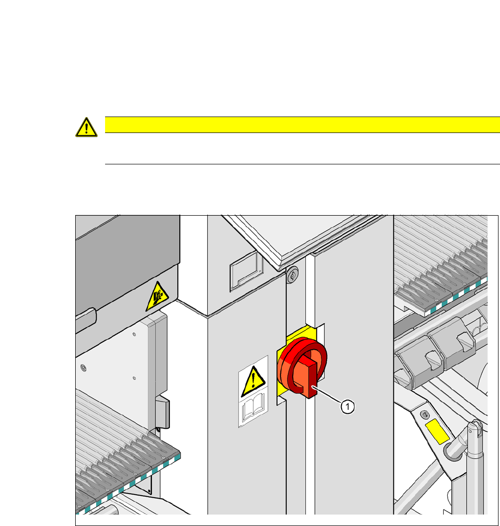
Fig. 2.11 - 1 Position of the power supply on the placement machine
2
CAUTION
Please note that each SWS module has its own main switch.
(1) Main switch