00197498-03_UM_SiplaceCA-Serie_EN.pdf - 第105页
User Manual SIPLACE CA-Series 2 Operational Safety From software version SC.708.0 Edition 12/20 14 EN -DRA FT 2.11 Energy State After Switching off Main Switch 105 2.1 1 Energy S t ate Af ter Switching off Main Switch 2 …
2 Operational Safety User Manual SIPLACE CA-Series
2.10 Disabling the Compressed Air Supply and Discharging the Pressure From software version SC.708.0 Edition 12/2014 EN -DRAFT
104
2
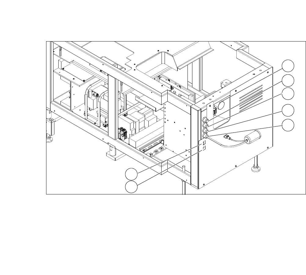
Fig. 2.10 - 2 Electrical and pneumatic connection on the SWS
2
(1) Manometer for compressed air supply (2) Voltage supply
(3) Communication with SIPLACE machine (4) CAN bus
(5) Compressed air connection (modified
adapter dummy connector [03011592-01])
(6) LAN1
(7) LAN2
2
1
3
4
5
6
7
User Manual SIPLACE CA-Series 2 Operational Safety
From software version SC.708.0 Edition 12/2014 EN -DRAFT 2.11 Energy State After Switching off Main Switch
105
2.11 Energy State After Switching off Main Switch
2
2.11.1 Main Switch on Placement Machines
2
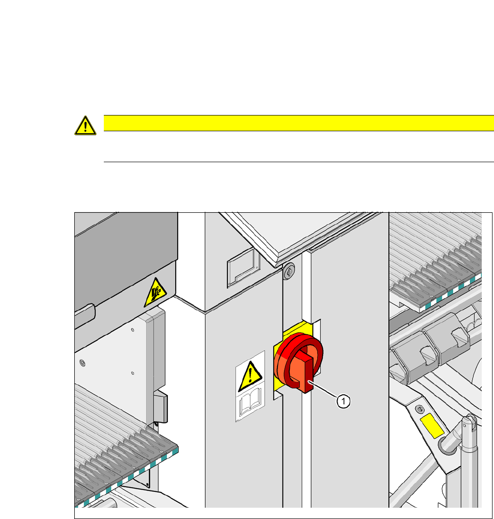
Fig. 2.11 - 1 Position of the power supply on the placement machine
2
CAUTION
Please note that each SWS module has its own main switch.
(1) Main switch

2 Operational Safety User Manual SIPLACE CA-Series
2.11 Energy State After Switching off Main Switch From software version SC.708.0 Edition 12/2014 EN -DRAFT
106
2
DANGER
Dangerous voltage levels!
The machine is supplied with 3 x 208 V~, 3 x 230 V~, 3 x 380 V~, 3 x 400 V~ or
3 x 415 V~ ± 5 %, 50/60 Hz mains voltage. Parts of the system therefore carry lethally
hazardous voltages - even when the main switch is switched off.
Incorrect handling of this machine can therefore result in death or severe injury or consid-
erable damage to equipment.
Always follow the applicable accident prevention and DIN regulations (particularly EN
60204, part 1 or IEC 60204, part 1) and the applicable regulations in your own coun-
try.
The covers over the power supply unit may ONLY be opened by appropriately quali-
fied and trained personnel.