00197498-03_UM_SiplaceCA-Serie_EN.pdf - 第112页
2 Operational Safety User Manual SIPLACE CA- Series 2.11 Energy State After Switching off Main Switch From software version SC.708.0 Edition 12/2014 EN -DRAFT 112 The following t able specifies the voltag es of modules w…
User Manual SIPLACE CA-Series 2 Operational Safety
From software version SC.708.0 Edition 12/2014 EN -DRAFT 2.11 Energy State After Switching off Main Switch
111
2
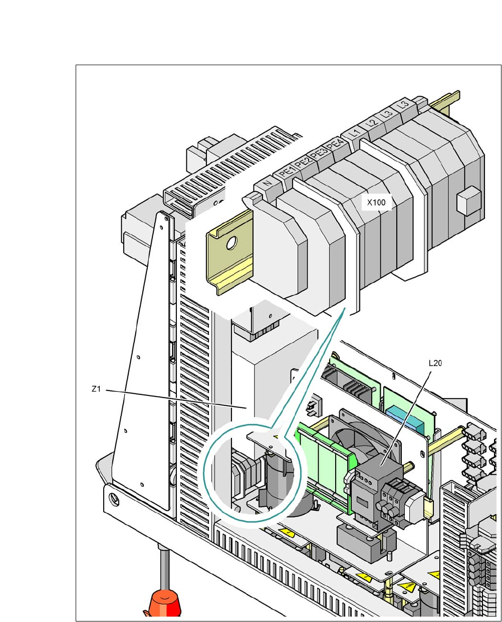
Fig. 2.11 - 5 Power supply unit, view from back
X100 Connection terminals for mains power supply cable
L20 Discharge inductor with fuses F21, F22 and F23
Z1 Mains filter
2 Operational Safety User Manual SIPLACE CA-Series
2.11 Energy State After Switching off Main Switch From software version SC.708.0 Edition 12/2014 EN -DRAFT
112
The following table specifies the voltages of modules when the machine is switched off at the main
switch, but still connected to the mains supply.
2
Module Voltage
Terminal panel X100
Mains filter Z1
Terminals L1, L2, L3
3 x 208 VAC
3 x 230 VAC
3 x 380 VAC
3 x 400 VAC
3 x 415 VAC
Service socket X102
120 VAC
130 VAC
220 VAC
230 VAC
240 VAC
Automatic circuit breaker F1
120 VAC
130 VAC
220 VAC
230 VAC
240 VAC
Main switch Q1
Terminals L1, L2, L3
3 x 208 VAC
3 x 230 VAC
3 x 380 VAC
3 x 400 VAC
3 x 415 VAC
Main switch Q1
Terminals T1, T2, T3
0 VAC
Power supply unit
(see item 5 of fig. 2.9 - 2
)
Test socketX11
GNDX12
Test socketX13_1
Test socketX13_4
GNDX13_7
< 10 VDC
< 10 VDC
< 10 VDC
Computer unit (see fig. 2.11 - 3
)
Test socket+ 12 VDC
Test socket- 12 VDC
Test socket+ 15 VDC
Test socket-15 VDC
Test socket+ 5 VDC
Test socket+ 52 VDC
Test socket+ 3.3 VDC
GND
0 VDC
0 VDC
0 VDC
0 VDC
0 VDC
0 VDC
0 VDC

User Manual SIPLACE CA-Series 2 Operational Safety
From software version SC.708.0 Edition 12/2014 EN -DRAFT 2.11 Energy State After Switching off Main Switch
113
2.11.1.2 Machine Switched off at Main Switch and Disconnected From Power
The machine is unpowered, apart from slight residual voltages in the power supply unit.
The SWS must be separately disconnected from the mains power supply!
2.11.1.3 Compressed Air Conditions in the Machine After Switching off at the Main
Power Switch
When you switch off the main switch (item 1 in fig. 2.11 - 1, page ) or if the power supply to the
machine fails, the electrically controlled main valve Y1 of the compressed air unit will be closed
(item 1 in fig. 2.10 - 1
). The pressure will drop to 0 MPa (0 bar) within 5 seconds.
2.11.2 Main Switch at the SWS
Each SWS has its own main switch for the voltage supply.