00197498-03_UM_SiplaceCA-Serie_EN.pdf - 第167页
User Manual SIPLACE CA-Series 3 Technical Data From software version SC.708.0 Edition 12/20 14 EN -DRAFT 3.8 Electrical and Pneumatic Connections 167 3.8.3 Electrical and Pneuma tic Connection on the SWS 3 Fig. 3.8 - 3 E…
3 Technical Data User Manual SIPLACE CA-Series
3.8 Electrical and Pneumatic Connections From software version SC.708.0 Edition 12/2014 EN -DRAFT
166
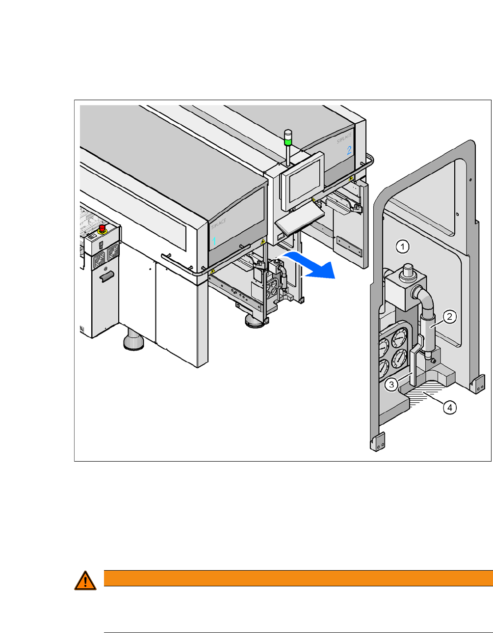
3.8.2 Pneumatic Connection on the Placement Machine
Fig. 3.8 - 2 Pneumatic Connection on the Placement Machine
(1) Pneumatic unit
(2) Connection coupling for the compressed air hose
(3) Shutoff valve
(4) Cutoff for the pneumatic hose
3
WARNING
Risk of injuries!
Risk of injuries from pressurized compressed air lines.
NEVER detach compressed air lines while they are still pressurized.
User Manual SIPLACE CA-Series 3 Technical Data
From software version SC.708.0 Edition 12/2014 EN -DRAFT 3.8 Electrical and Pneumatic Connections
167
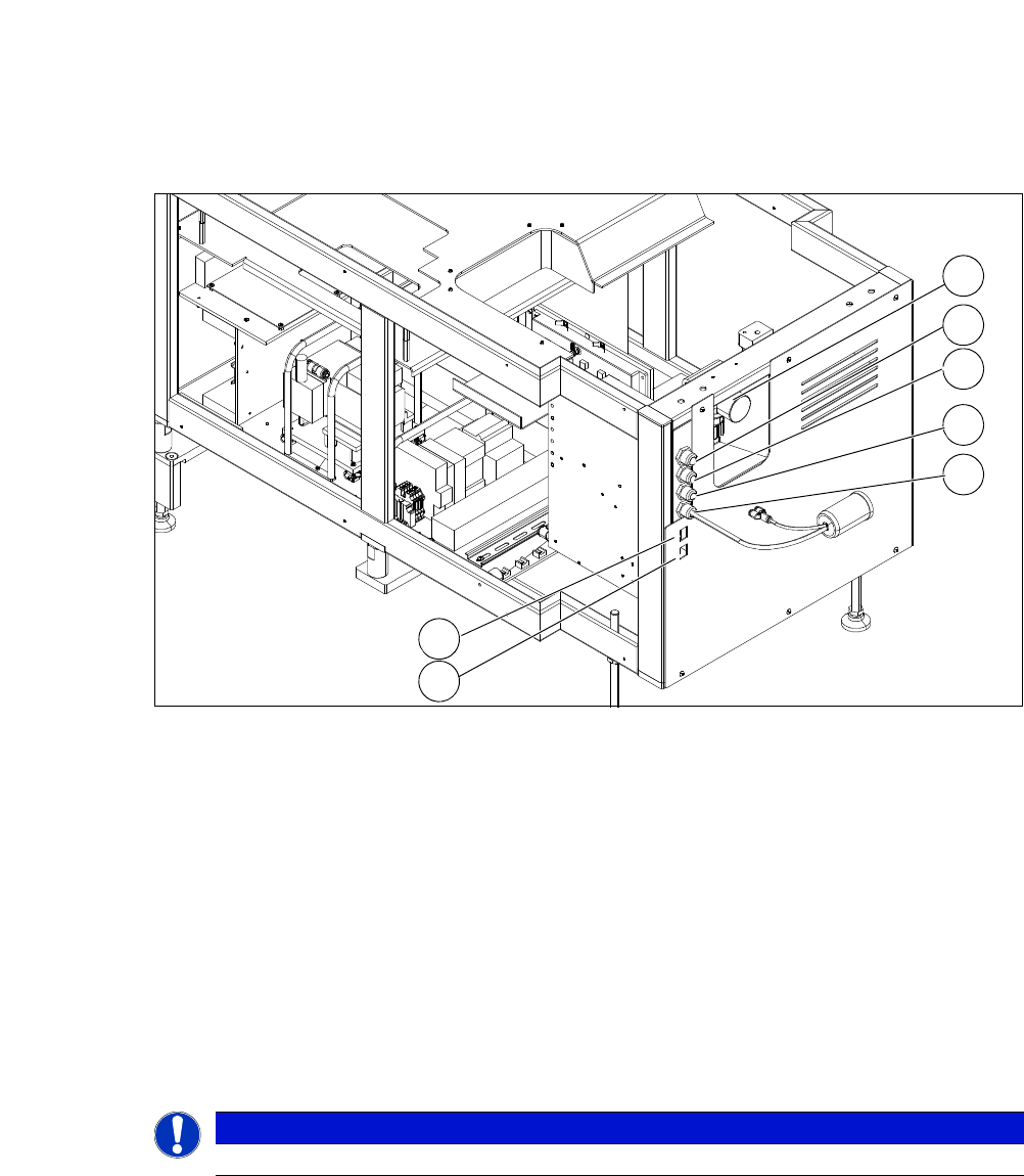
3.8.3 Electrical and Pneumatic Connection on the SWS
3
Fig. 3.8 - 3 Electrical and pneumatic connection on the SWS
3
3
3
(1) Manometer for compressed air supply (2) Voltage supply
(3) Communication with SIPLACE machine (4) CAN bus
(5) Compressed air connection (modified
adapter dummy connector [03011592-01])
(6) LAN1
(7) LAN2
PLEASE NOTE
The connection points of the SWS can be easily accessed when the unit is not installed.
2
1
3
4
5
6
7
3 Technical Data User Manual SIPLACE CA-Series
3.9 Controls on the Placement Machine From software version SC.708.0 Edition 12/2014 EN -DRAFT
168
3.9 Controls on the Placement Machine
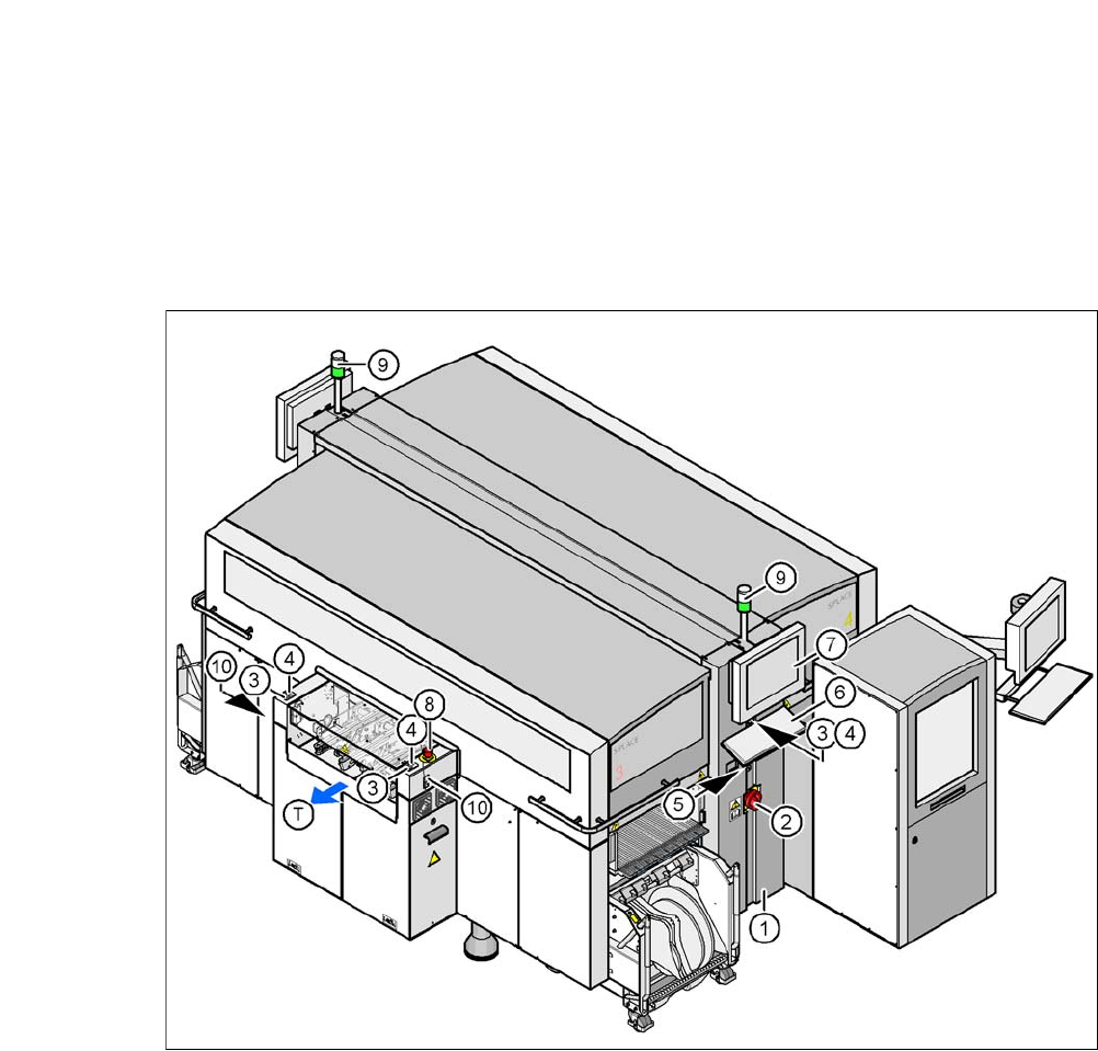
3.9.1 Controls and Displays
3
Fig. 3.9 - 1 Controls and displays
(1) Operator panel on the power supply side (7) LCD touchscreen
(2) Main switch (8) EMERGENCY STOP button
(3) Stop button (black) (9) Indicator lamps
(4) Start button (white) (10) Button for docking and undocking the
component trolley
(5) Component counter
(6) Keyboard (T) Direction of PCB transport