00197498-03_UM_SiplaceCA-Serie_EN.pdf - 第171页
User Manual SIPLACE CA-Series 3 Technical Data From software version SC.708.0 Edition 12/20 14 EN -DRAFT 3.9 Controls on the Placement Machine 171 3.9.3.1 Controls on the Machine's Operator Panels The two operator p…

3 Technical Data User Manual SIPLACE CA-Series
3.9 Controls on the Placement Machine From software version SC.708.0 Edition 12/2014 EN -DRAFT
170
Indicator lamps 3
The sequence of colors of the indicator lamps is white - green. These lamps are used to signal
operating statuses and malfunctions of the machine.
3.9.3 Ergonomic Arrangement of Controls
Fig. 3.9 - 1, page 168 gives an overview of where the controls are located. They are subdivided
into the following groups:
Operator panel on right side (pneumatic unit) of the central compartment with 3
– LCD touchscreen
– Keyboard with trackball
– Start button, Stop button
Operator panel on left side (power supply unit) of the central compartment with 3
– LCD touchscreen
– Keyboard with trackball
– Component counter
– Start button
– Stop button
– Main switch
PCB conveyor input and output sides with 3
– EMERGENCY STOP button
– Start button, Stop button
– Button for docking and undocking the component trolley

User Manual SIPLACE CA-Series 3 Technical Data
From software version SC.708.0 Edition 12/2014 EN -DRAFT 3.9 Controls on the Placement Machine
171
3.9.3.1 Controls on the Machine's Operator Panels
The two operator panel have identical control functions.
Monitor, keyboard, start and stop buttons 3
Both sides of the placement machine feature a monitor screen and keyboard.
The start and stop buttons are located beneath the keyboard. The on-screen dialog will occasion-
ally prompt you to activate certain actions using buttons, and this arrangement will make it easier
for you both to activate and to interactively control these actions.
Main switch 3
The main power switch is part of the power module. It is located on the left-hand operator panel
viewed in the direction of PCB transport. It is located here because it is only needed for servicing
and preventive maintenance work and is therefore not subject to frequent use.
3.9.3.2 Controls on the Input and Output Sides of the Placement Machine
The controls on the input and output sides of the placement machine are identical.
EMERGENCY STOP button, start and stop buttons 3
There is an EMERGENCY STOP button and a start and stop button on both the input and the out-
put sides of the PCB conveyor. The arrangement of the buttons has been designed for quick and
easy access from any position.
3 Technical Data User Manual SIPLACE CA-Series
3.10 Controls on the SWS From software version SC.708.0 Edition 12/2014 EN -DRAFT
172
3.10 Controls on the SWS
Each SWS features a monitor screen and keyboard.
The EMERGENCY STOP button is located on one side of the SWS together with the other con-
trols.
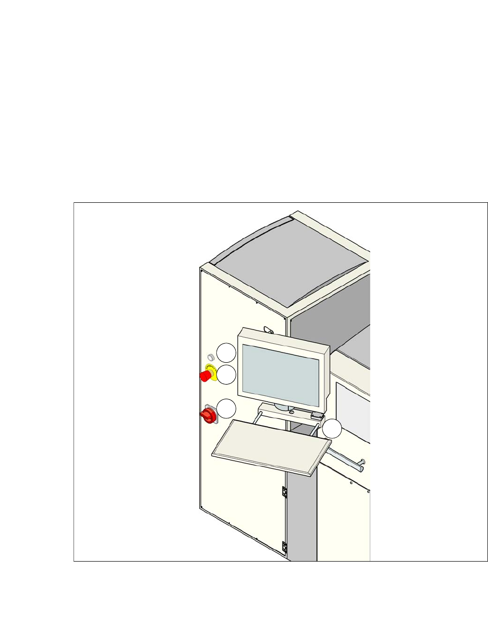
3.10.1 Controls and Displays
3
Fig. 3.10 - 1 Controls and displays
(1) Operating status (3) Power supply switch
(2) EMERGENCY STOP switch (4) Monitor screen with keyboard
1
2
3
4