00197498-03_UM_SiplaceCA-Serie_EN.pdf - 第173页
User Manual SIPLACE CA-Series 3 Technical Data From software version SC.708.0 Edition 12/20 14 EN -DRAFT 3.10 Controls on the SWS 173 3.10.2 Description All the controls can be reached by a 1.40 m t all person. EMERGENCY…
3 Technical Data User Manual SIPLACE CA-Series
3.10 Controls on the SWS From software version SC.708.0 Edition 12/2014 EN -DRAFT
172
3.10 Controls on the SWS
Each SWS features a monitor screen and keyboard.
The EMERGENCY STOP button is located on one side of the SWS together with the other con-
trols.
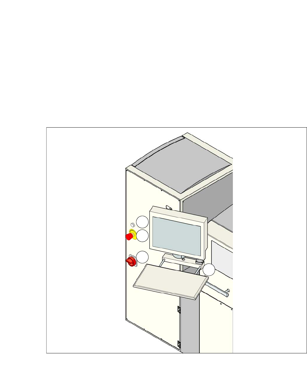
3.10.1 Controls and Displays
3
Fig. 3.10 - 1 Controls and displays
(1) Operating status (3) Power supply switch
(2) EMERGENCY STOP switch (4) Monitor screen with keyboard
1
2
3
4
User Manual SIPLACE CA-Series 3 Technical Data
From software version SC.708.0 Edition 12/2014 EN -DRAFT 3.10 Controls on the SWS
173
3.10.2 Description
All the controls can be reached by a 1.40 m tall person.
EMERGENCY STOP button 3
When you press the EMERGENCY STOP button, it engages. SWS and SIPLACE perform an
EMERGENCY STOP. The power supply to all SWS axes is interrupted. Turn the button to release
it.
3
Operating status indicator on the SWS 3
The operating status shines if the SWS is switched on.
Main switch 3
The main switch is used for switching the power supply to the SWS on and off.
3
LCD monitor 3
Each SWS features a flat screen monitor with LCD technology and touchscreen function.
Keyboard 3
The keyboard is located beneath the monitor. The keyboard is fitted with a USB port which can be
used for backup of data to an external storage medium.
DANGER
Lethal voltages!
Even when the EMERGENCY STOP button is switched off, some parts inside the ma-
chine carry potentially lethal voltages.
Always follow the applicable accident prevention and DIN regulations (particularly EN
60204, part 1 or IEC 60204, part 1) and the applicable regulations in your own coun-
try.
Only qualified or appropriately trained personnel may switch the power supply to the
placement machine on and off.
DANGER
Lethal voltages!
Some parts inside the machine carry potentially lethal voltages - even when switched off
at the main power switch.
Always follow the applicable accident prevention and DIN regulations (particularly EN
60204, part 1 or IEC 60204, part 1) and the applicable regulations in your own coun-
try.
Only qualified or appropriately trained personnel may switch the power supply to the
placement machine on and off.
3 Technical Data User Manual SIPLACE CA-Series
3.11 Gantries From software version SC.708.0 Edition 12/2014 EN -DRAFT
174
3.11 Gantries
The gantry system consists of two functional groups
–X axis and
–Y axis
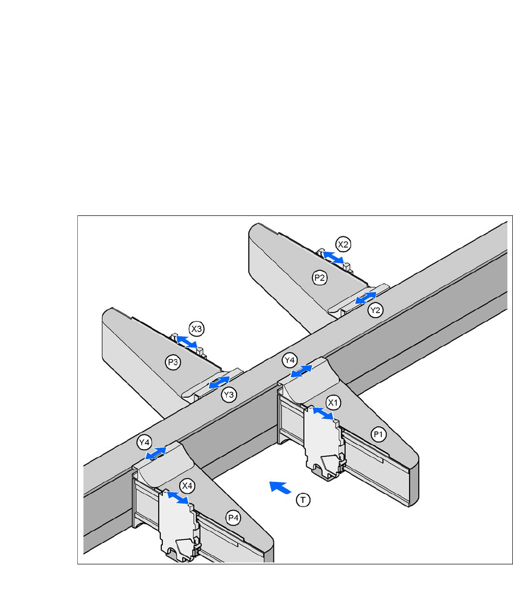
3.11.1 Position of Gantry in CA4 Machines
3
Fig. 3.11 - 1 Position of Gantry in CA4 Machines
P1, P2, P3, P4 (gantry 1 - 4) X3X axis, gantry 3
X1X axis, gantry 1 Y3Y axis, gantry 3
Y1Y axis, gantry 1 X4X axis, gantry 4
X2X axis, gantry 2 Y4Y axis, gantry 4
Y2Y axis, gantry 2 (T)Direction of PCB transport
Placement area 2
Placement area 1