00197498-03_UM_SiplaceCA-Serie_EN.pdf - 第177页
User Manual SIPLACE CA-Series 3 Technical Data From software version SC.708.0 Edition 12/20 14 EN -DRAFT 3.11 Gantries 177 3.1 1.4 Structure of the Y Axis 3 Fig. 3.1 1 - 3 Y axis struct ure (1) Y linear mo tor (primary p…

3 Technical Data User Manual SIPLACE CA-Series
3.11 Gantries From software version SC.708.0 Edition 12/2014 EN -DRAFT
176
The X axis mainly consists of the following modules:
– Gantry arm (1)
– Head mount with X axis linear motor (primary part) (2)
– Linear distance measuring system (3)
– Guidance system (4)
– Permanent magnet (secondary part of the X axis linear motor) (5)
– Trailing cable (8)
3
The head mount (2) takes up the following components:
– Sub-gantry camera (PCB camera of PCB Vision module) (6)
– Set of head boards (7)
– Measuring head for measuring system
– Placement head
The gantry arm (item 1 in fig. 3.11 - 2
) is made of a carbon fiber composite. This technology allows
assemblies to be made with extremely low weight and high rigidity.
The X axis is driven by a linear motor. The secondary part of the drive consists of a permanent
magnet and is mounted on the gantry arm. The primary part is bolted to the head mount. The head
mount is designed to work with all placement head types - another reason for the high flexibility
achieved with SIPLACE placement machines.
3.11.3 Technical Data for the X Axis
3
Drive Direct, linear motor
Maximum speed 2.5 m/s
Travel range 480 mm
Distance measuring system Linear metal scale
Length of scale 520 mm
Resolution 1 µm
User Manual SIPLACE CA-Series 3 Technical Data
From software version SC.708.0 Edition 12/2014 EN -DRAFT 3.11 Gantries
177
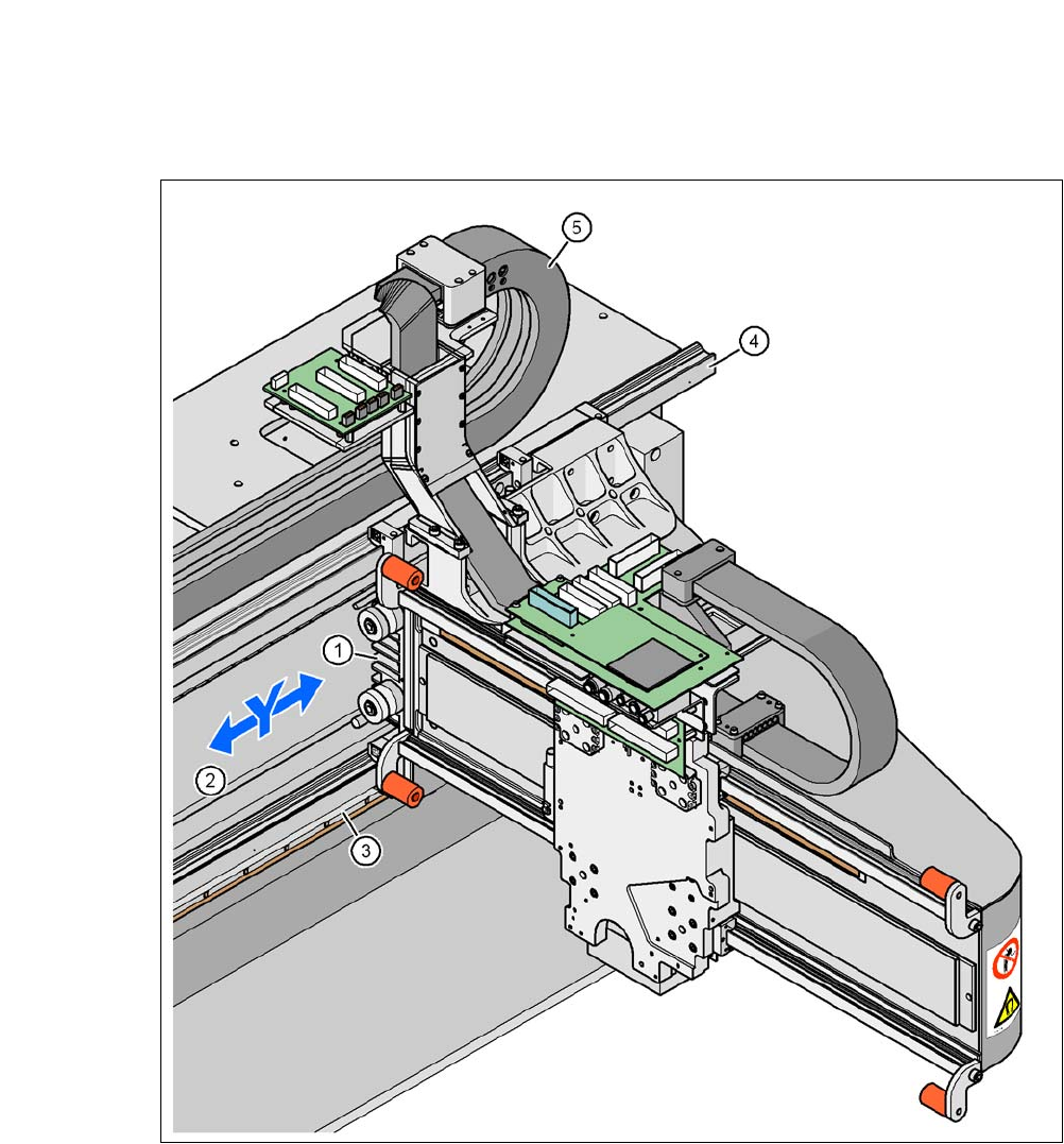
3.11.4 Structure of the Y Axis
3
Fig. 3.11 - 3 Y axis structure
(1) Y linear motor (primary part)
(2) Permanent magnet (secondary part of the Y axis linear motor)
(3) Linear distance measuring system
(4) Guidance system
(5) Trailing cable

3 Technical Data User Manual SIPLACE CA-Series
3.11 Gantries From software version SC.708.0 Edition 12/2014 EN -DRAFT
178
The Y axis mainly consists of the following modules:
– Y axis linear motor (primary part) (1)
– Permanent magnet (secondary part of the Y axis linear motor) (2)
– Linear distance measuring system (3)
– Guidance system (4)
– Trailing cable (5)
The Y axis is driven by a linear motor. The secondary part of the drive is made up of permanent
magnets and is mounted on the machine frame. The primary part is bolted to the gantry.
3.11.5 Technical Data for the Y Axis
Drive Direct, linear motor
Maximum speed 2.5 m/s
Travel range 1430 mm
Distance measuring system Linear metal scale
Length of scale 1850 mm
Resolution 1 µm