00197498-03_UM_SiplaceCA-Serie_EN.pdf - 第180页
3 Technical Data User Manual SIPLACE CA-Series 3.12 Vision Cameras From software version SC.708.0 Edition 12/2014 EN -DRAFT 180 3.12.1 Component Camera C&P , T ype 41, 6 x 6, Digital Item no.: 0307 8957-xx 3.12.1.1 S…

User Manual SIPLACE CA-Series 3 Technical Data
From software version SC.708.0 Edition 12/2014 EN -DRAFT 3.12 Vision Cameras
179
3.12 Vision Cameras
A component camera is integrated at each Collect&Place head (see fig. 3.7 - 2 page 144).
With the help of the component Vision module, the system determines
– the precise position of the components at the nozzle and
– the geometry of the component shape.
The PCB cameras are fixed to the bottom of the gantries. With the help of fiducials on the feeder
modules , you can determine the exact pick-up position of components, which is particularly im-
portant for small components.
The PCB Vision module uses fiducials on the boards to determine
– the position of the board,
– its rotation angle
– and its distortion.
3 Technical Data User Manual SIPLACE CA-Series
3.12 Vision Cameras From software version SC.708.0 Edition 12/2014 EN -DRAFT
180
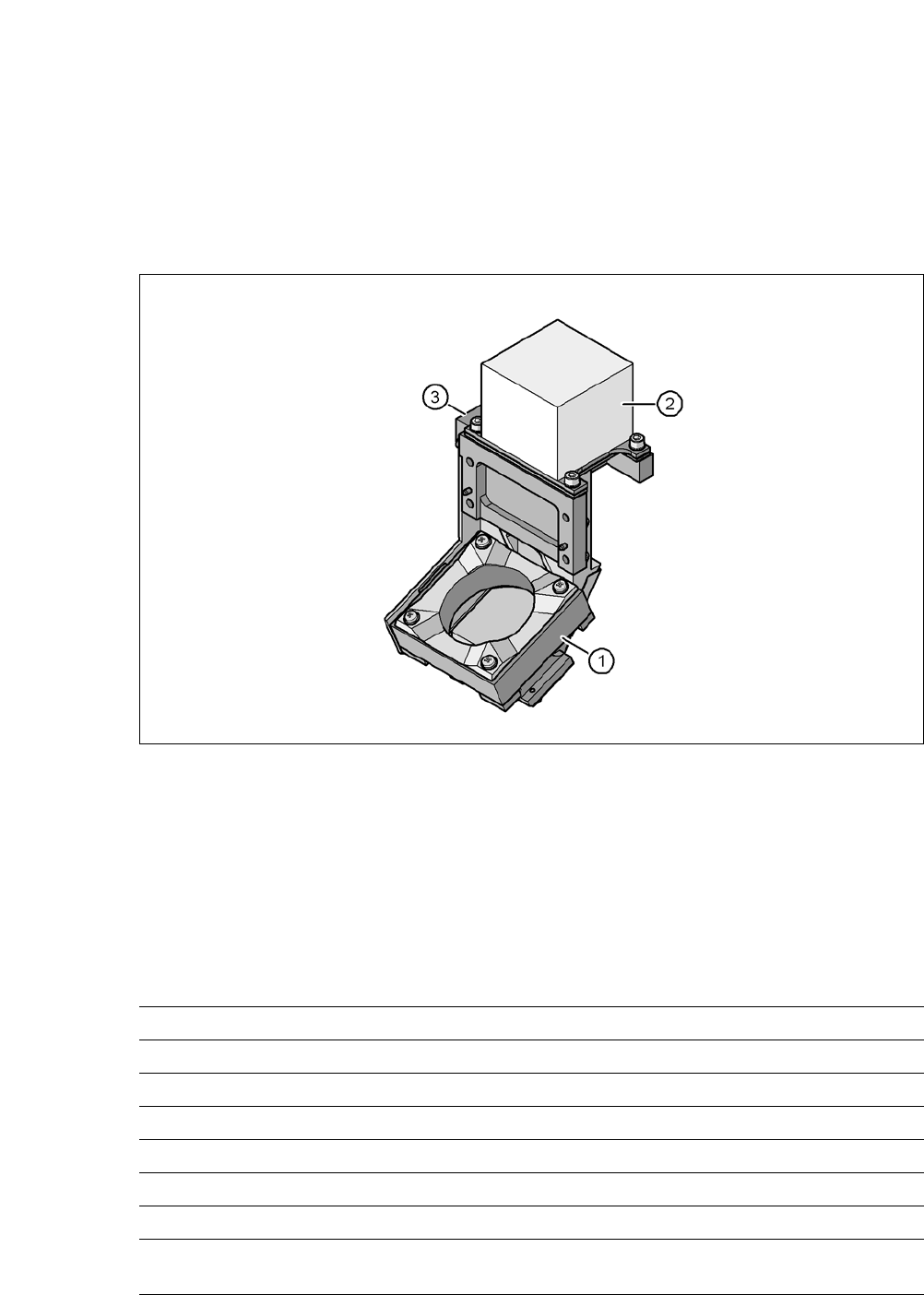
3.12.1 Component Camera C&P, Type 41, 6 x 6, Digital
Item no.: 03078957-xx
3.12.1.1 Structure
3
Fig. 3.12 - 1 Component camera C&P, type 41, 6 x 6, digital
3
(1) Component camera lens and illumination
(2) Camera amplifier
(3) Illumination control
3.12.1.2 Technical Data
3
Component dimensions 0.3 mm x 0.15 mm to 6 mm x 6 mm
Component range Flip chip (min. thickness 50 µm): 0.8 mm x 0.8 mm
Min. lead pitch 0.08 mm
Min. lead width 0.03 mm
Min. ball pitch 0.10 mm
Min. ball diameter 0.05 mm
Field of vision 8.9 mm x 8.9 mm
Illumination mode Front-illumination (5 levels, programmable as re-
quired)
User Manual SIPLACE CA-Series 3 Technical Data
From software version SC.708.0 Edition 12/2014 EN -DRAFT 3.12 Vision Cameras
181
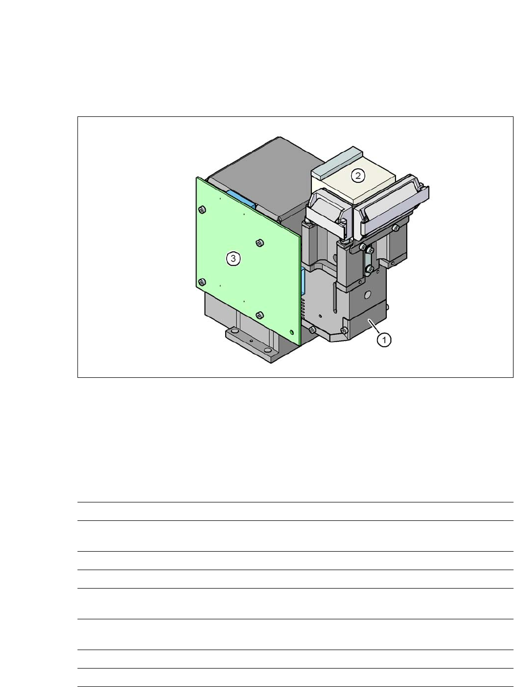
3.12.2 C&P Component Camera, type 30, 27 x 27, Digital
3.12.2.1 Structure
3
Fig. 3.12 - 2 C&P Component Camera, type 30, 27 x 27, Digital
(1) Component camera lens and illumination
(2) Camera amplifier
(3) Illumination control
3.12.2.2 Technical Data
3
Component dimensions 0.3 x 0.3 mm² to 27 x 27 mm²
Component range 01005 to 27 x 27 mm²
PLCC, SO, QFP, TSDP, SOT, MELF, CHIP, IC, BGA
Min. lead pitch 0.3 mm
Min. lead width 0.15 mm
Min. ball pitch 0.25 mm for components < 18 x 18 mm²
0.35 mm for components ≥ 18 x 18 mm²
Min. ball diameter 0.14 mm for components < 18 x 18 mm²
0.2 mm for components ≥ 18 x 18 mm²
Field of vision 32 x 32 mm²
Illumination mode Front-illumination (5 levels, programmable as required)