00197498-03_UM_SiplaceCA-Serie_EN.pdf - 第181页
User Manual SIPLACE CA-Series 3 Technical Data From software version SC.708.0 Edition 12/20 14 EN -DRAFT 3.12 Vision Cameras 181 3.12.2 C&P Component Camera, type 30, 27 x 27, Digital 3.12.2.1 Structure 3 Fig. 3.12 -…
3 Technical Data User Manual SIPLACE CA-Series
3.12 Vision Cameras From software version SC.708.0 Edition 12/2014 EN -DRAFT
180
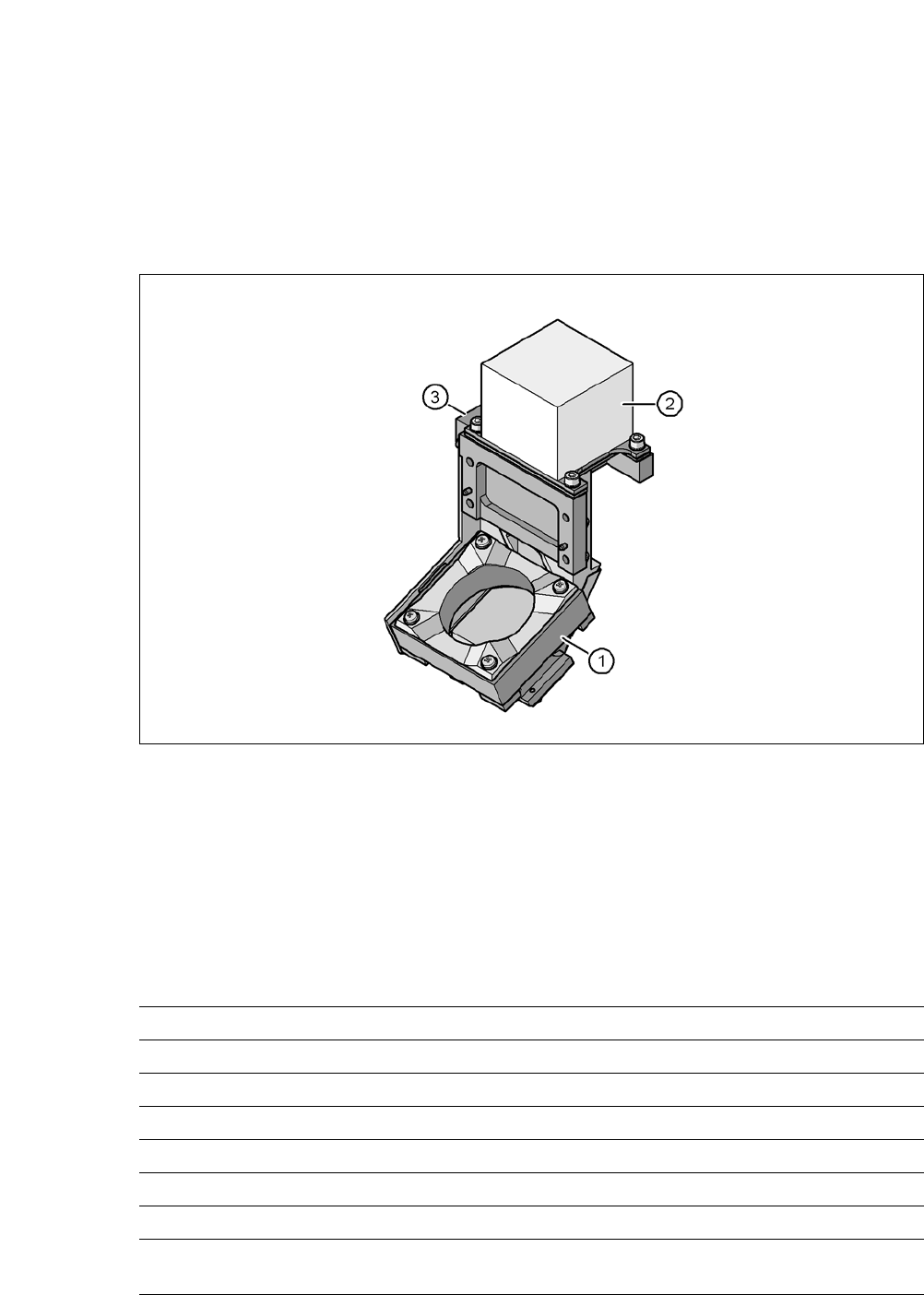
3.12.1 Component Camera C&P, Type 41, 6 x 6, Digital
Item no.: 03078957-xx
3.12.1.1 Structure
3
Fig. 3.12 - 1 Component camera C&P, type 41, 6 x 6, digital
3
(1) Component camera lens and illumination
(2) Camera amplifier
(3) Illumination control
3.12.1.2 Technical Data
3
Component dimensions 0.3 mm x 0.15 mm to 6 mm x 6 mm
Component range Flip chip (min. thickness 50 µm): 0.8 mm x 0.8 mm
Min. lead pitch 0.08 mm
Min. lead width 0.03 mm
Min. ball pitch 0.10 mm
Min. ball diameter 0.05 mm
Field of vision 8.9 mm x 8.9 mm
Illumination mode Front-illumination (5 levels, programmable as re-
quired)
User Manual SIPLACE CA-Series 3 Technical Data
From software version SC.708.0 Edition 12/2014 EN -DRAFT 3.12 Vision Cameras
181
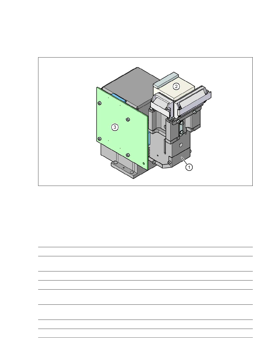
3.12.2 C&P Component Camera, type 30, 27 x 27, Digital
3.12.2.1 Structure
3
Fig. 3.12 - 2 C&P Component Camera, type 30, 27 x 27, Digital
(1) Component camera lens and illumination
(2) Camera amplifier
(3) Illumination control
3.12.2.2 Technical Data
3
Component dimensions 0.3 x 0.3 mm² to 27 x 27 mm²
Component range 01005 to 27 x 27 mm²
PLCC, SO, QFP, TSDP, SOT, MELF, CHIP, IC, BGA
Min. lead pitch 0.3 mm
Min. lead width 0.15 mm
Min. ball pitch 0.25 mm for components < 18 x 18 mm²
0.35 mm for components ≥ 18 x 18 mm²
Min. ball diameter 0.14 mm for components < 18 x 18 mm²
0.2 mm for components ≥ 18 x 18 mm²
Field of vision 32 x 32 mm²
Illumination mode Front-illumination (5 levels, programmable as required)
3 Technical Data User Manual SIPLACE CA-Series
3.12 Vision Cameras From software version SC.708.0 Edition 12/2014 EN -DRAFT
182
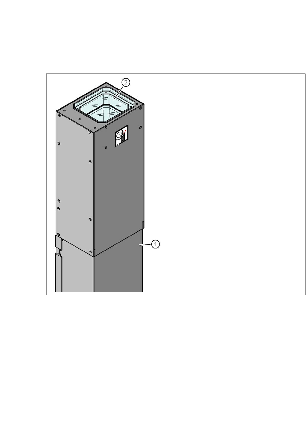
3.12.3 Component Camera, Stationary P&P, Type 33, 55 x 45, Digital
3.12.3.1 Structure
3
Fig. 3.12 - 3 Structure for the stationary P&P component camera, type 33, 55 x 45, digital
3.12.3.2 Technical Data
3
(1) Camera housing with integral camera
and camera amplifier
(2) Glass plate - illumination and lens levels
below
Component dimensions 0.5 x 0.5 mm² to 55 x 45 mm²
Component range 0402, MELF, SO, PLCC, QFP, electrolytic capacitors, BGA
Min. lead pitch 0.3 mm
Min. lead width 0.15 mm
Min. ball pitch 0.35 mm
Min. ball diameter 0.2 mm
Field of vision 65 x 50 mm²
Illumination mode Front-illumination (6 levels, programmable as required)